


Physical Features 13
10/100/1000BASE-T Ports
1000BASE-T only operates in full duplex mode.
10/100BASE-TX can be in half or full duplex mode.
Gigabit Combo Ports
(5) Power LED
The Power LED shows the power status of the Switch.
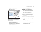
(6) Self-adhesive Pads
The unit is supplied with four self-adhesive rubber pads.
Do not apply the pads if you intend to rack mount the
unit.
If the unit is to be part of a free-standing stack, apply
the pads to each marked corner area on the underside
of the unit. Place the unit on top of the lower unit,
ensuring that the pads locate with the recesses of the
lower unit.
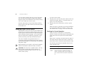
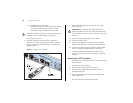
Rear Panel
The rear panel of the Switch contains a power supply
socket and a recovery button.
(7) Power Socket
The Switch automatically adjusts to the supply voltage.
Only use the power cord that is supplied with the unit.
(8) Recovery Button
The recovery button reinitializes the Switch. This returns
the Switch to the factory default settings if, for
example, you have forgotten the default IP address, or
forgotten your user name or password.
CAUTION: 3Com recommends that you back up your
configuration settings before you recover the Switch,
otherwise your configuration may be lost. Refer to
“Resetting to Factory Defaults” on page 73 for details.
Status Meaning
Yellow The port is operating in full duplex mode.
Off The port is operating in half duplex mode.
Status Meaning
Green SFP is inserted in the slot.
Off No SFP in the slot.
Status Meaning
Green The unit is powered on and ready for use.
Yellow Internal power, POST, or loopback test has
failed. Switch is in fail-safe mode.
Off The unit is not receiving power.
■ Check that the power cord is connected cor-
rectly.
■ If the unit still does not operate, contact your
supplier.