


Connecting Interface Cables 67
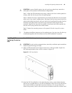
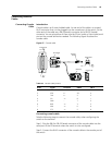
Connecting AUX cable
Step 1: Plug the RJ-45 connector of the AUX cable into the AUX port of the
switch.
Step 2: Plug the DB-25 (male) or DB-9 (male) connector at the other end into the
serial port of the analog modem.
Connecting Category-5
Shielded Cable
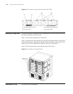
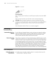
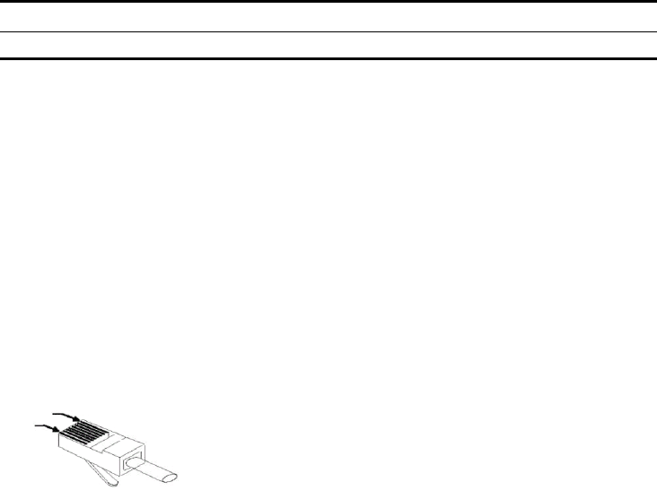
Introduction to RJ-45 connector
Being RJ-45 connector, the 10Base-T/100Base-TX port of the Switch 8800 Family
supports MDI/MDIX auto-sensing and will be connected using the category-5
shielded cable. The following figure illustrates an RJ-45 connector.
Figure 49 RJ45 connector
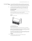
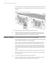
Connecting category-5 shielded cable
Step 1: Plug one end of the network cable into the desired Ethernet RJ-45
connector on the switch.
Step 2: Plug the other end of the cable into the RJ-45 port of the peer device.
Connecting Fiber
n
All the megabit and gigabit optical modules available for the Switch 8800 Family
are SFP modules that provide LC user ports.
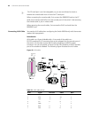
Introduction to fiber connector
n
■ When selecting a fiber network facility, make sure that the type of the
connector and the fiber match the adopted optical port.
■ Before connecting the fiber, make sure that the receive-end optical power does
not exceed the upper threshold of the receiving optical power. Excessive
receiving optical power is very likely to burn the optical module.
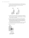
Fiber connectors are indispensable passive components in an optical fiber
communication system. Their application allows the removable connection
between optical channels, which makes the optical system debugging and
maintenance more convenient and the transit dispatching of the system more
flexible. Among various fiber connectors, only LC connector will be introduced
here.
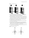
■ LC fiber connector
8 CTS ← 5 8
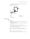
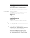
Table 70 AUX cable pinouts
RJ-45 Signal Direction DB-25 DB-9
PIN #8
PIN #1