


8e6 enterprise reporter Quick start Guide 53
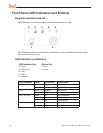
Front of Chassis: Control Panel
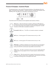
Control panel buttons, icons, and LED indicators display on the right side of the front
panel. The buttons let you perform a function on the unit, while an LED indicator corre-
sponding to an icon alerts you to the status of that feature on the unit.
The buttons and LED indicators for the depicted icons function as follows:
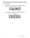
UID (button) – When the UID button is pressed, a steady blue LED displays on
both the front and rear of the chassis (see also Rear of Chassis). These indicators
are used for easy location of the chassis in a large stack conguration. The LED
remains on until the button is pressed a second time.
Overheat/Fan Fail (icon) – This LED is unlit unless the chassis is overheated.
NIC2 (icon) – A ashing green LED indicates network activity on LAN2.
NIC1 (icon) – A ashing green LED indicates network activity on LAN1.
HDD (icon) – In addition to displaying in the control panel, this icon also displays
on the front panel on each hard drive carrier. A green LED indicates hard drive
activity. An unlit LED on a drive carrier may indicate a hard drive failure.
Power (icon) – The LED is unlit when the server is turned off. A steady green LED
indicates power is being supplied to the unit’s power supplies. (See also Rear of
Chassis.)
Power (button) – When the power button is pressed, the main power to the server
is turned on. When the power button is pressed again, the main power to the server
is removed but standby power is still supplied to the server.