


Publication 1760-GR001C-EN-P - April 2005
Drawing a Circuit with Pico 2-5
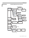
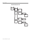
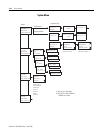
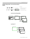
Pico Circuit Diagram
Elements
Contacts
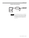
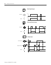
Contacts are used to modify the flow of current in the circuit diagram.
Contacts in the circuit diagram are either make or break contacts.
Make contacts are open when off (de-energized) and closed when on.
Break contacts are closed when off and open when on.
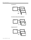
Pico works with different contacts, which can be used in any order in
the contact fields of the circuit diagram.
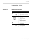
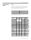
Contact Pico Representation
Make contact; Open when off I, Q, M, A, C, T, P, D, S, :, R
Break contact; Closed when off I
, Q, M, A, C, T, P, D, S, R
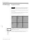
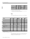
Contact Type Make
Contact
Break
Contact
1760-L12xxx 1760-L18xxx
1760-L20xxx
Controller Inputs I I
I1 to I8 I1 to I12
0 signal I13 I13
Expansion Status –
I14
(3)
Short-circuit/overload I16 I15 to I16
Soft Inputs - Keypad P P
P1 to P4 P1 to P4
Controller Outputs Q Q
Q1 to Q4 Q1 to Q8
Internal Marker Bits M M
M1 to M16 M1 to M16
Internal Marker Bits N N
N1 to N16 N1 to N16
Counters C C
C1 to C16 C1 to C16
Timers T T
T1 to T16 T1 to T16
Real Time Clock
(1)
Analog Setpoint
Compare
(2)
AAA1 to A16 A1 to A16
Text Display D D
D1 to D16 D1 to D16
Expansion Outputs or
Internal Marker Bits
SS
S1 to S8 S1 to S8
Jump to Label : – :1 to :8 :1 to :8
Expansion Inputs R R
–R1 to R12
Expansion Overload
Detection
RR
–
R15 and R16
(3)
1 to 8 1 to 8