


Publication 1760-GR001C-EN-P - April 2005
Index
A
accessories A-3
Allen-Bradley
contacting for assistance
Preface-iii
support Preface-iii
Analog comparator 2-18
B
Basic circuit
Exclusive OR circuit (XOR)
2-24
Flip-flop output 2-23
Impulse relay 2-23
Motor start/stop circuit 2-25
Negation (NOR) 2-23
Permanent contact 2-23
Series connection (AND) 2-24
Break contact 2-5
Buttons 1-10
Use in circuit diagrams 2-1
C
Cable 3-3
Change operating mode 2-4
Circuit diagram
Access relay parameters
2-21
Choosing relay type 2-10
Displaying 2-9
Example 2-9, 2-20
Inserting contacts 2-9
Loading 3-2
Select marker relay 2-20
Storing 3-2
Symbols 1-14
Testing 2-11
Using a function relay 2-20
Using buttons in 2-1
Circuit diagram elements 2-5
Coil function 2-8
common techniques used in this manual
Preface-ii
contacting Allen-Bradley for assistance
Preface-iii
Contactor function 2-8
Contacts
Overview
2-5
Counter relay 2-16
Parameter display 2-16
Cursor display 1-13
D
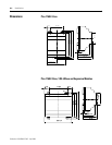
dimensions
1760-L12
A-4
1760-L18 A-4
1760-L20 A-4
1760-OW2 A-5
1760-RM A-5
expansion modules A-4
E
Example
Basic circuits
2-23
Circuit diagram 2-9
Contacts and relays 2-9
Example of function relay 2-20
F
Function relays
Analog comparator
2-18
Counter relay 2-16
Overview 2-13
Text display 2-19
Time switch 2-17
Timing relay 2-13
K
Keypad 1-10
L
Logic tables 2-23
M
Make contact 2-5
manuals, related Preface-ii
Memory Module (optional) 3-1
Menu guidance 1-11
Menu structure 1-15
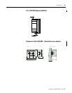
Mounting 1-3
O
Operating buttons 1-10
P
Parameter display
Analog comparator
2-18
Counter relay 2-16
For timing relays 2-15
Time switch 2-17