


Publication 1760-GR001C-EN-P - April 2005
2-6 Drawing a Circuit with Pico
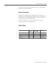
Relays
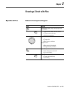
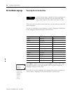
Pico has thirteen different types of relay for use in a circuit diagram.
The switching behavior of these relays is set using coil functions and
parameters. The coil functions and parameters are listed with the
description of each function relay type.
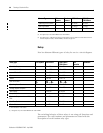
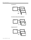
Operating Hours Counter O O O1 to O4 O1 to O4
Year Time Switch Y Y
Y1 to Y8 Y1 to Y8
Master Reset Z Z
Z1 to Z3 Z1 to Z3
(1) Not available on “-NC” models.
(2) This applies only to the 1760-LxxBWB-xx and 1760-L12DWD.
(3) This applies only to 1760-L18xxx-EX models. R15 and R16 are used for expansion overload detection for the
transistor expansion module, 1760-IB12XOB8, as described on page 9-4.
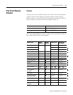
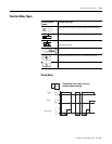
Contact Type Make
Contact
Break
Contact
1760-L12xxx 1760-L18xxx
1760-L20xxx
Relay type Pico Symbol 1760-L12xxx 1760-L18xxx
1760-L20xxx
Coil
Function
Parameter
Controller Outputs Q Q1 to Q8 Q1 to Q8 X –
Internal Marker Bits M M1 to M16 M1 to M16 X –
Internal Marker Bits N N1 to N16 N1 to N16 X –
Counters C C1 to C16 C1 to C16 X X
Timers T T1 to T16 T1 to T16 X X
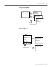
Real Time Clock
(1)
–X
Operating Hours Counters O O1 to O4 O1 to O4 X X
Analog Setpoint Compare
(2)
A A1 to A16 A1 to A16 – X
Text Display D D1 to D16 D1 to D16 X X
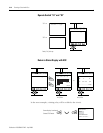
Jump to Label : :1 to :8 :1 to :8 X –
Expansion Outputs or Internal Marker
Bits
S S1 to S8 (as marker) S1 to S8 X –
Year Time Switch Y Y1 to Y8 Y1 to Y8 – X
Master Reset Z Z1 to Z3 Z1 to Z3 X –
(1) Not available on “-NC” models.
(2) This applies only to the 1760-LxxBWB-xx and 1760-L12DWD.
1 to 8 1 to 8