


ENGLISH
12
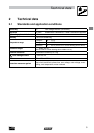
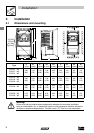
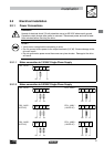
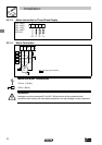
Installation
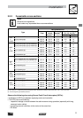
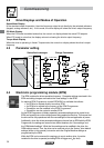
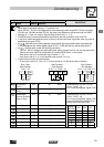
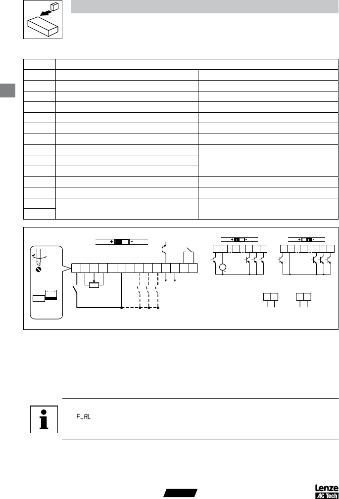
3.2.3 Control terminals
Terminal Data for control connections
1
Digital Input: Start/Stop input resistance = 4.
3
kΩ
2
Analog Common
5
Analog Input: 0...
1
0 VDC input resistance: >50 kΩ
6
Internal DC supply for speed pot +
1
0 VDC, max. 10 mA
25
Analog Input: 4...20 mA input resistance: 250Ω
4
Digital Reference/Common +1
5 VDC / 0 VDC, depending on assertion level
11
Internal DC supply for external devices +
1
2 VDC, max. 50 mA
13A
Digital Input: Configurable with P1
21
input resistance = 4.3k
Ω
13B
Digital Input: Configurable with P
1
22
13C
Digital Input: Configurable with P1
23
14
Digital Output: Configurable with P1
42 DC 24 V / 50 mA; NPN
30
Analog Output: Configurable with P1
50…P155 0…10 VDC, max. 20 mA
16
Relay output: Configurable with P1
40
AC 250 V / 3 A
DC 24 V / 2 A … 240 V / 0.22 A, non-inductive
17
6 25 4 11
13A
13B
13C
17
51 2
14 30
16
AOUT
DIGOUT
2k … 10k
+10 V
AIN
AIN
COM
COM
ALsw
252
4 … 20 mA
52
0 … 10 V
0 … 5 V
1 2 4
13A
13B
13C
+12 VDC - 0 %
…
+30 VDC + 0 %
ALsw
+15V
1 2 4
13A
13B
13C
ALsw
COM
PNP NPN
4.5 lb-in
(0.5 Nm)
0.25 in (6 mm)
AWG 26…16
(<1mm²)
V0109
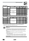
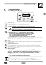
Assertion level of digital inputs
The digital inputs can be configured for active-high or active-low by setting the Assertion Level
Switch (ALsw) and P120. If wiring to the drive inputs with dry contacts or with PNP solid state
switches, set the switch and P120 to “High” (+). If using NPN devices for inputs, set both to “Low”
(-). Active-high (+) is the default setting.
HIGH = +12 … +30 V
LOW = 0 … +3
V
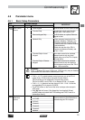
Note
An fault will occur if the Assertion Level switch (ALsw) position does not match the
parameter P120 setting and P100 or any of the digital inputs (P121...P123) is set to a
value other than 0.