


Quick Installation GuideCheetahSwitch Workgroup-2027
2 3
Mounting the Switch
This switch can be placed directly on your desktop, or mounted in a rack.
Before you start installing the switch, make sure you can provide the right operating
environment, including power requirements, sufficient physical space, and proximity
to other network devices that are to be connected. Verify the following installation
requirements:
Power requirements: 100 to 240 VAC (± 10%) at 50 to 60 Hz (± 3Hz). The
switch's power supply automatically adjusts to the input voltage level.
The switch should be located in a cool dry place, with at least 10 cm. (4 in.) of
space at the front and back for ventilation.
Place the switch out of direct sunlight, and away from heat sources or areas with
a high amount of electromagnetic interference.
If you intend to mount the switch in a rack, make sure you have all the necessary
mounting screws, brackets, bolts and nuts, and the right tools.
Check if network cables and connectors needed for installation are available.
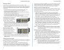
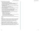
Stacking Switches on a Flat Surface
The CheetahSwitch can be stacked
anywhere there is a enough flat space,
such as on a table or desktop.
1. Stick the self-adhesive rubber foot
pads (that come with this package)
on each of the 4 concave spaces located on the bottom of the first switch.
2. Place the first switch on a firm flat surface where you want to install the stack.
3. Repeat step 1 for each switch before stacking them. The rubber foot pads
cushion the switch against shock/vibrations and provide space between each
switch for ventilation.
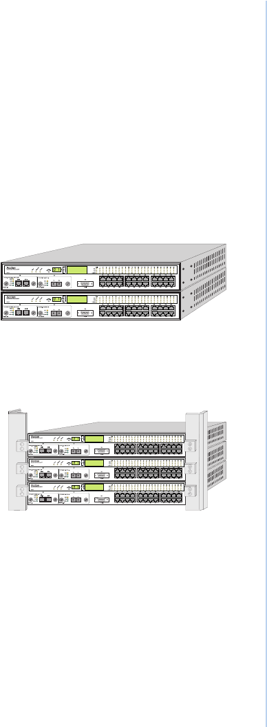
Mounting Switches in a Rack
Please comply with the following
instructions to ensure that your switch
is securely mounted in the rack.
1. Use a standard EIA 19-inch rack.
2. Use the brackets and screws supplied
in the rack mounting kit.
3. Use a cross-head screwdriver to attach the brackets to the side of the switch.
4. Position the switch in the rack by lining up the holes in the brackets with the
appropriate holes on the rack, and then use the supplied screws to mount the
switch in the rack.
Connecting the Switch System
The CheetahSwitch has 24 RJ-45 ports and one AUI port that support connection to
standard 10 Mbps Ethernet. It also has two slots for installing optional 100BASE-TX
or 100BASE-FX Fast Ethernet Uplink Modules.
All ports support full or half-duplex operation. The transmission mode for the
10BASE-T, AUI and 100BASE-FX ports must be manually configured using the
configure button or console interface. (See "Configuring the Switch" on page 7.)
The transmission mode can be set for the 100BASE-TX ports using auto-negotiation
(if also supported by the attached device). However, if the devices attached to
these ports do not support auto-negotiation, you can manually configure the port to
match the transmission mode used by the attached device. You can also set the
switching mode for any of the switch's ports to cut-through or store-and-forward
using the console interface. (See Using the Console Program on page 7.)
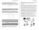
Making a Connection via an MDI-X Station Port
You can connect any RJ-45 (MDI-X) station port on the switch to any device that
uses a standard network interface such as a workstation or server, or to a network
interconnection device such as a bridge or router (depending on the port type
implemented on that device).
1. Prepare the devices you wish to network. Make sure you have installed
10BASE-T or 100BASE-TX network interface cards for connecting to the
switch's RJ-45 (MDI-X) station ports. You also need to prepare straight-through
shielded or unshielded twisted-pair cables with RJ-45 plugs at both ends. Use
100W Category 3, 4 or 5 cable for standard 10 Mbps Ethernet connections, or
100W Category 5 cable for 100 Mbps Fast Ethernet connections.
2. Connect one end of the cable to the RJ-45 port of the network interface card,
and the other end to any available (MDI-X) station port on the switch. RJ-45 Ports
1 - 24 support 10 Mbps Ethernet connections (in addition to the AUI Port). If you
ordered the 100BASE-TX uplink module, then you can also attach the switch to
a 100 Mbps Fast Ethernet device. When inserting an RJ-45 plug, be sure the
tab on the plug clicks into position to ensure that it is properly seated. Using the
switch in a stand-alone configuration, you can network up to 27 end nodes.
I Do not plug a phone jack connector into any RJ-45 port. This may damage the
switch. Instead, use only twisted-pair cables with RJ-45 connectors that
conform with FCC standards.
Notes: 1. Make sure each twisted-pair cable does not exceed 100 meters (328 feet).
2. We advise using Category 5 cable for all network connections to avoid
any confusion or inconvenience in the future when you upgrade attached
devices to Fast Ethernet.
Making a Connection via the MDI Daisy-Chain Port
1. To make a direct connection to another compatible switch or repeater hub,
connect any RJ-45 (MDI-X) port on the switch to an MDI daisy-chain port on the
other device. If you have a 100BASE-TX uplink module installed, then you can
link to another switch or hub by running a cable from MDI-X to MDI ports on
either device. (See "Connecting to an Uplink Module" on page 4.)
2. Prepare straight-through shielded or unshielded twisted-pair cables with RJ-45
plugs at both ends. Use 100W Category 3, 4 or 5 cable for standard 10 Mbps
Ethernet connections, or 100W Category 5 cable for 100 Mbps Fast Ethernet
connections. When inserting an RJ-45 plug, be sure the tab on the plug clicks
into position to ensure that it is properly seated.
Notes: 1. Make sure each twisted-pair cable does not exceed 100 meters (328 feet).
2. To connect to another switch or hub, you may also attach to (MDI-X)
station ports at both ends if you use crossover cabling.
3. To achieve best performance when cascading switches, group devices or
segments that communicate most frequently on the same switch, and
reserve the Fast Ethernet uplinks for connecting to the larger network.