


Quick Installation GuideCheetahSwitch Workgroup-2027
6 7
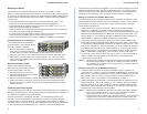
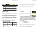
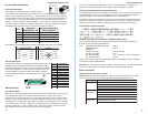
Verifying Port Status
Check each connection by viewing the port status indicators shown in the following
figure and table.
DEL etatS noitacidnI
rewoPnO.rewopgniviecersihctiwS
citsongaiDnO.margorpcitsongaidgninnursihctiwS
elosnoCnO.tropelosnocehtotdetcennocsiecivedrehtororotinoM
LOCgnihsalFehttaatadtimsnartotdetpmettasecivederomroowT
).DC/AMSCtenrehtErednunoitautislamroN(.emitemas
XDFnO.edomxelpud-llufottesneebevahsnoitacinummoC
tcA/kniLnO.noitcennockrowtendilavadehsilbatsesahtroP
gnihsalF.tropehtgnisrevartsiciffarT
001
1
nO.spbM001ottesneebevahsnoitacinummoC
.eludomknilpuXT-ESAB001ehtnosraeppaylnorotacidnisihT-1
Verifying System Operation
Verify that all attached devices have a valid connection. The switch monitors the
link status for each port. If any device is properly connected to the switch and
transmitting a link beat signal, the Link indicator will light up for the corresponding
port. If the Link indicator fails to light when you connect a device to the switch,
check the following items:
Both sides of each connection must use the same transmission mode (i.e., half
or full duplex). If a device is connected to the 10BASE-T or 100BASE-FX ports,
then you must manually set the transmission mode using the on-board
configuration program. (See "Configuring the Switch" on page 7.) If any device
connected to the 100BASE-TX ports does not support auto-negotiation and
cannot operate at half duplex (i.e., the system default when auto-negotiation
fails), then you must also manually set the transmission mode using the
configure button or on-board configuration program.
Be sure all network cables and connectors are properly attached to the
connected device and the switch.
See if your cable is functioning properly by using it for another port and attached
device that displays valid indications when connected to the network.
Verify that you have not exceeded the specified limits for any attached media
type as summarized in the following table:
epyTaideM htgneLxaM sedoNxaM rehtO
riaPdetsiwT)teef823(sretem0010001
tenrehtEnihT)teef706(sretem58103sretem5.0
1
tenrehtEkcihT)selim3.0(sretem005005sretem05
2
)spbM01(citpOrebiF)selim42.1(sretem0002riapknil
)spbM001(citpOrebiF)selim52.0(m214:xelpudflah
)selim42.1(m0002:xelpudlluf
riapknil
.sedonneewtebecnatsidmuminiM-1
.reviecsnartottropIUAmorfelbacpordfohtgnelmumixaM-2
)teef461=sretem05;teef46.1=sretem5.0(
Configuring the Switch
The transmission mode for all ports must be set to the same mode used by the
connected device. Ports 1 - 25 and the 100BASE-FX Uplink Module must be
manually configured; but the system can use auto-negotiation to determine the
transmission mode for the 100BASE-TX Uplink Module. However, if any device
connected to this module does not support auto-negotiation, and a link cannot be
established using half duplex (i.e., the last state tested by auto-negotiation), then
you must manually set the transmission mode for the concerned port to half or full
duplex using the configure button or console configuration program.
Notes: 1. Full duplex can only be used for a dedicated link. When connecting to a
shared collision domain (e.g., a repeater hub) be sure the transmission
mode is set for half duplex.
2. This switch uses the NWays standard for auto-negotiation.
If you connect a terminal or PC to the console port on the back of the switch, then
you can perform the following tasks:
Enable/disable any port
Set the communication mode for any port
Set the switching mode to cut-through or store-and-forward
Restart the system
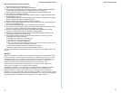
Displaying Port Utilization History
The switch can display a history of LAN bandwidth utilization for any port (selected
with the configure button). A graph showing the percentage of valid data (compared
to available bandwidth) that has passed through the selected port over the past 20
seconds is shown on the LED array located to the right of the displayed port number.
Just use a short press (1 second) on the configure button to scan through the port
numbers and display the current ports utilization.
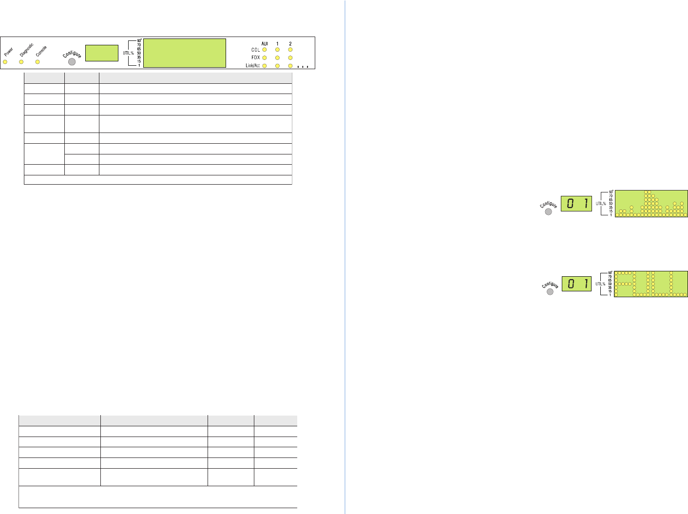
Using the Configure Button
The switch can set the transmission mode for any port (selected with the configure
button). Use a short press (1second) to scan through the port numbers. When the
required port number is displayed, use a long press (3 seconds) to display the
current communication mode on the LED matrix to the right of the port number. To
change modes, use a short press to scan through the available options. Ports 1 -
25 support half and full duplex; while Ports 26 - 27 support 10 or 100 Mbps, as well
as half or full duplex and auto-negotiation (if the attached also supports this feature).
When the required mode is displayed on the front panel, use another long press to
enable your selection.
Notes: 1. The configuration options for the 10 Mbps ports includes half duplex, full
duplex or auto-negotiation.
2. Options for the optional 100 Mbps uplink ports cover both speed and
mode, as well as full auto-negotiation.
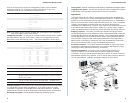
Using the Console Program
Establishing a Connection
- Attach a VT100 compatible terminal or a PC running
a terminal emulation program to the DB9 serial port on the back of the switch. Use
the RS232 null-modem cable provided with this package, or use a null modem
connection that complies with the wiring assignments shown on page 11. When
attaching to a PC, set terminal emulation type to VT100, specify the port used by
your PC (i.e., COM 1~4), and then set communications to 8 data bits, 1 stop bit, no
parity, and 9600 bps. Also be sure to set flow control to "none."