


Quick Installation GuideCheetahSwitch Workgroup-2027
4 5
Restrictions on Cascade Length - Because the CheetahSwitch breaks up the
path for connected devices into separate collision domains, it has no restrictions on
cascade length. Therefore, when cascading devices other than this switch, do not
include it or any connected cabling in your calculations for cascade length.
Making a Connection via the AUI Port
The AUI port is used for connection to the following 10 Mbps media types:
Thin Ethernet (10BASE2)
Thick Ethernet (10BASE5)
Remote fiber optic link (10BASE-F)
Thin Ethernet - Attach a BNC transceiver to the AUI port and plug the BNC T-type
connector into a BNC port on the transceiver. When connecting two devices via
BNC ports, there should be at least 0.5 meters (1.64 feet) of coaxial cable between
the two BNC ports. A thin Ethernet coaxial cable segment can be extended up to
185 meters (607 feet) and can link up to 30 nodes. If the unit is at the terminal end
of a trunk segment, connect a 50W terminator to the open end of the "T" connector.
Note: Thin Ethernet only supports half-duplex communications.
Thick Ethernet - Attach an AUI to 10BASE5 transceiver to the thick Ethernet trunk,
and then run an AUI drop cable (with 15-pin D-type connectors on both ends)
between the AUI port on the switch and the transceiver. Note that the maximum
length of an AUI drop cable is 50 meters (164 feet). A thick Ethernet segment can
be extended up to 500 meters (1640 feet) and can link up to 100 nodes.
Note: Thick Ethernet only supports half-duplex communications.
Fiber Optic - If you plan to use the AUI port for connecting fiber optic cable, attach
a fiber optic transceiver (MAU) to the AUI port, and then connect the transceiver to
the remote device. Note that 10 Mbps fiber can be extended up to two kilometers
(1.24 miles), regardless of whether you are running the link at half or full duplex.
Note: Your fiber optic transceiver may or may not support full-duplex
communication, depending on the manufacturer.
Connecting to an Uplink Module
Additional network expansion can be achieved by inserting an optional
100BASE-TX or 100BASE-FX Uplink Module into either of the slots on the front
panel. These Fast Ethernet modules act as a two-port switch (i.e., for external
connection and for interfacing with the internal switching hardware).
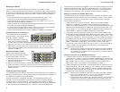
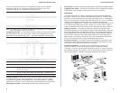
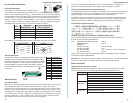
The 100BASE-TX module supports connection to
either 10 Mbps Ethernet or 100 Mbps Fast Ethernet
by automatically adjusting to the transmission speed
of the attached device. It provides both RJ-45
MDI-X and MDI ports to simplify connection to end-
node devices with a standard Ethernet interface
(using the MDI-X port) or to another compatible
switch or hub (using an MDI to MDI-X connection).
Both SC and ST type modules are provided for
100BASE-FX. These modules run at 100 Mbps.
Using either of these fiber modules, you can run
a fiber optic link up to two kilometers (1.24 miles)
when using full duplex, or up to 412 meters (0.25
miles) with half duplex.
The 100BASE-TX Uplink Module can set the transmission mode to full or half
duplex via auto-negotiation. However if the attached device does not support auto-
negotiation, you can manually configure the connected port to half or full duplex using
the configure button or console interface. (See "Configuring the Switch" on page 7.)
I The uplink modules are not hot-swappable. Be sure you power off the switch
before installing any of these modules.
Installing an Uplink Module - You can install an uplink module as described below:
1. Disconnect power to the switch.
2. Remove the face plate on the expansion slot (or a previously installed uplink
module) by removing the two screws with a cross-head (Phillips) screwdriver.
3. Before opening the package that contains the uplink module, touch the bag to
the switch casing to discharge any potential static electricity.
4. Remove the module from the anti-static shielded bag.
5. Holding the module level, gently push it all the way into the expansion slot,
ensuring that it firmly engages with the connector.
6. If you are sure the module is properly mated with the connector, replace the
retainer screws to secure the module in the expansion slot.
7. Run corresponding media type between the uplink module and the target device.
Connecting Twisted-pair Cabling - If you will be using the 100BASE-TX module,
prepare Category 5 straight-through twisted-pair cable with RJ-45 plugs at both
ends. When connecting the module directly to an end-node device (e.g., a
workstation or file server), a bridge or router, run cable from the MDI-X port on the
uplink module to the target device. However, when connecting the module to a
compatible switch or hub, connect one end of the cable to the MDI port on the
uplink module, and the other end to an MDI-X port on the target device (or vice
versa). When inserting an RJ-45 plug, be sure the tab on the plug clicks into
position to ensure that it is properly seated. Note that as a general rule, the length
of any twisted-pair cable should not exceed 100 meters (328 feet).
Connecting Fiber Optic Cabling - If you are using a 100BASE-FX module,
prepare fiber optic cable with SC or ST connectors at both ends. When connecting
the module directly to an end-node device (e.g., a workstation or file server), run
cable from the Rx (Tx) port on the module to the Tx (Rx) port on the target device.
When inserting the cable, be sure the tab on the plug clicks into position to ensure
that it is properly seated. Note that as a general rule, the length of fiber optic cable
should not exceed 2 kilometers (1.24 miles) when the link is operated at full duplex
or 412 meters (0.25 miles) for half duplex.
Powering on the Switch
1. Plug the power cord into the power socket at the rear of the switch, and the
other end into a power outlet.
2. Check the LED marked Power on the front panel to see if it is on. The unit will
automatically select the setting that matches the connected input voltage.
Therefore, no additional adjustments are necessary when connecting it to any
input voltage within the range marked on the rear panel.
3. The switch performs a self-diagnostic test upon power-on. (Note that this test
takes about 15 seconds to complete.)
Note: The unit supports a "hot remove" feature which permits you to connect/
disconnect cables without powering off the switch and without disrupting the
operation of the devices attached to the switch.