Fast SwitcHub-2se User’s Guide
Setup and Configuration 2-3
Making Fiber Optic Connections
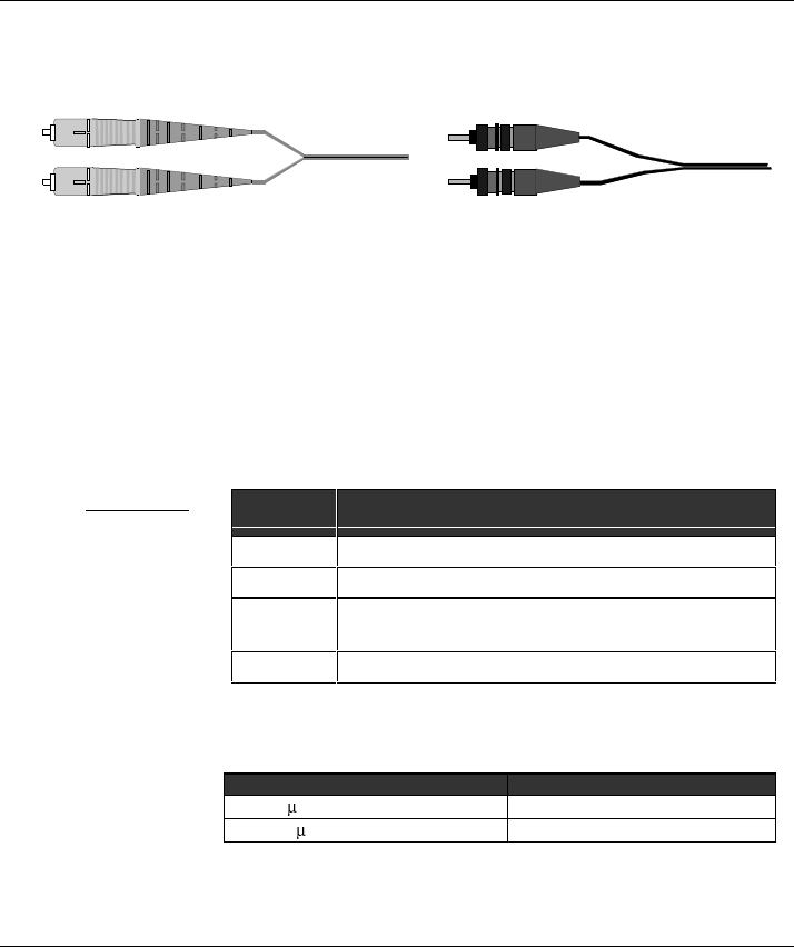
1. Prepare a pair of fiber-optic cables with SC or ST type connectors at both ends.
SC-Type Connector ST-Type Connector
2. If you are making a connection to a server or workstation, be sure it that has
a properly installed 100BASE-FX network interface card. Connect the Rx/Tx
jacks on the target device to the Tx/Rx jacks on the switch.
Distance Limit and Power Loss in Fiber Optics - When using fiber optic cabling,
the maximum length between two switches can be up to 2 kilometers.
However, you must consider power loss when calculating the actual length of
cable that can be used with your system. You can calculate power loss with the
following formula:
m =
(p dB - i dB)
c dB/km
Variable Description
m cable length (kilometers)
p dB power budget
i dB intervening devices
(e.g., patch cables and splices)
c dB/km loss per kilometer of cable
Note: To determine the power loss incurred by intervening devices and specific cable
type, inquire with the manufacturer. The power budget depends on the gauge of cable
as shown below.
Gauge of Fiber Cable Power Budget
50/125 m
9.2 dB
62.5/125 m
13 dB
