


Altos 1100 Series User’s Guide
2
F
Fast POST mode, 2-18
Features, 1-1, 3-3
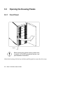
Front panel, 3-3, 3-6
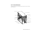
Internal structure, 3-5
Rear panel, 3-4
Front panel, 3-3, 3-6
Front panel connectors, 1-9
Floppy drive A, 2-5
Floppy drive B, 2-5
Floppy drives, 2-12
H
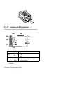
Hard disk drive cage, 3-13
Jumpers and connectors, 3-14
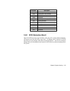
SCSI backplane board, 3-15
I
IDE drives, 2-12
Advanced PIO mode, 2-14
CD-ROM drive DMA mode, 2-15
Hard disk 32-bit access, 2-15
Hard disk block mode, 2-14
Hard disk size > 504 MB, 2-14
IDE primary channel master, 2-6
IDE primary channel slave, 2-6
IDE secondary channel master, 2-6
IDE secondary channel slave, 2-6
Initialize SCSI before IDE, 2-19
Installing 32 bit PCI cards, 1-20
Installing a DIMM, 1-18
Installing an AGP card, 1-21
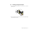
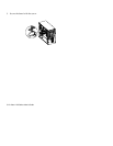
Installing an expansion board, 3-11
Installing expansion cards, 1-20
32 bit PCI cards, installing, 1-20
AGP card, installing, 1-21
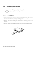
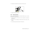
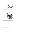
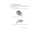
Installing disk drives, 3-8
3.5-inch drive, 3-8
5.25-inch drives, 3-9
Installing optional components, 1-10
ESD precautions, 1-11
Instructions, post-installation, 1-12
Instructions, pre-installation, 1-11
Installing the Pentium II processor,
1-13
Installing the RDM module, 1-23
Installing the termination board, 1-
16
Internal cache, 2-5, 2-33
Internal structure, 3-5
J
Jumper and connector locations, 1-5
Jumper settings, 1-6
Jumpers and connectors, 1-5, 3-14
Functions, connector, 1-7
Locations, 1-5
Settings, jumper, 1-6
L
Leaving setup, 2-49
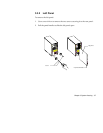
Left panel, 3-7
Load setup default settings, 2-48
M
Main board ID, 2-9
Main board S/N, 2-9
Major components, 1-3