


Chapter 3 System Housing
3-5
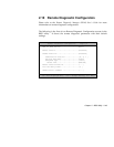
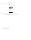
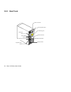
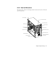
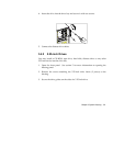
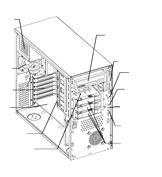
3.2.3 Internal Structure
The figure below shows the housing internal structure and some of the basic
system components.
P
ower Supply
Expansion Slot
Brackets
B
ackplane Board
Hot-Swap Cage
(SCSI)
5.25-inch Drive Bays
Expansion Card
Housing Fan
3.5-inch Drive Bay
Hard Disk Drive LED
Power Switch
S
ystem Status LED
Power LED
R
emovable Hard Disk
D
rive Trays