


Chapter 5 111
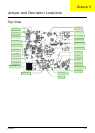
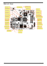
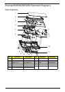
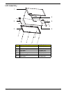
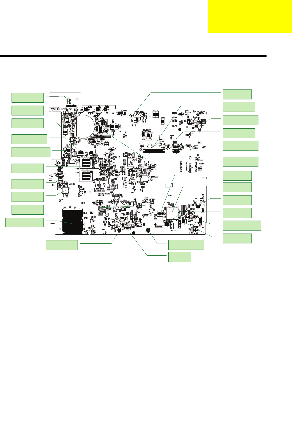
Jumper and Connector Locations
Top View
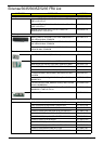
Glide PAD FFC Conn
PU5 Thermal protection
CN4/ Int. SPK. Conn.
CN2/ K/B FFC conn.
PU2 +1.5VSUS PWM
U17 System BIOS
U14/ EC/ KBC
Y3/ KBC X’tal
Glide PAD Left SW
CN9/ BT wire
Y4 S.B X’tal.
U4 LAN EEPROM IC
U11 HDMI lever shift
CN1 LCD wire Conn
U7/U9 Dis VRAM
U13 Clock generator
U16 Acer ID ROM
PU1/ SM BUS IC
Glide PAD Right SW
U2 / LAN control IC
CN8 / Ext USB wire Conn
U5 / CPU thermal IC
CN7 Card reader Conn
U10 Fan control IC,
PU3 / Charge PWM IC
Chapter 5