


SPEC NO.
MT220WW 01 V.0
PAGE
13/23
ALL RIGHTS RESERVED ANY PORTION OF THIS DOCUMENT SHALL NOT BE REPRODUCED, COPIED, OR TRANSFORMED
TO ANY OTHER FORMS WITHOUT
PRIOR
WRITTEN
PERMISSION FROM INNOLUX DISPLAY CORPORATION.
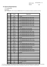
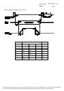
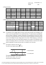
d. Display Position
D(1, 1) D(2, 1) …… D(840, 1) …… D(1679, 1) D(1680, 1)
D(1, 2) D(2, 2) …… D(840, 2) …… D(1679, 2) D(1680, 2)
.
.
.
……
.
.
.
……
.
.
.
.
.
.
D(1, 525) D(2, 525) …… D(840, 525)
…… D(1679, 525)
D(1680, 525)
.
.
.
……
.
.
.
……
.
.
.
.
.
.
D(1, 1049)
D(2, 1049)
…… D(840, 1049)
…… D(1679, 1049)
D(1680, 1049)
D(1, 1050)
D(2,1050) …… D(840, 1050)
…… D(1679,1050)
D(1680, 1050)
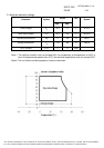
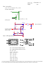
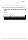
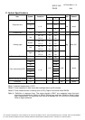
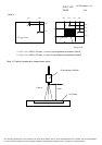
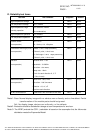
e. Backlight driving conditions
Parameter Symbol
Min. Typ. Max. Unit Remark
Remark
Lamp voltage VL 758(8mA)
794(7mA)
955(3mA)
Vrms
Lamp operation current
IL 3 7 8 mArms
Note 1
1250 T = 25±D
!
Note 2,3,4,5
!
Lamp starting voltage VLstart
1570
Vrms
T = 0±D
Note 2,3,4,5
Frequency F 40 55 80 KHZ Note 5
Lamp life time 40000 Hr Note 6
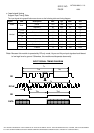
Note: The waveform of the voltage output of inverter must be area-symmetric and the design of the
inverter must have specifications for the modularized lamp. The performance of the Backlight,
such as lifetime or brightness, is greatly influenced by the characteristics of the DC-AC inverter
for the lamp. All the parameters of an inverter should be carefully designed to avoid producing too
much current leakage from high voltage output of the inverter. When designing or ordering the
inverter please make sure that a poor lighting caused by the mismatch of the Backlight and the
inverter (miss-lighting, flicker, etc.) never occurs. If the above situation is confirmed, the module
should be operated in the same manners when it is installed in your instrument.
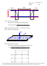
Note 1 :
The degree of unbalance: less than 10%
The ratio of wave height: less than 10%2 ±
The degree of unbalance = |
I
p
-
I
-p
| /Irms*100(%)
The ratio of wave height =
I
p
(or
I
-p
)/Irms
Lamp should be completely turned on.
I
p
I
-p
I
p
: high side peak
I
-p
: low side
peak