


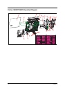
105 Chapter 5
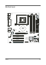
Jumper and Connector Description
Jumper Setting
NOTE: *: Default Settings.
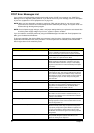
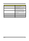
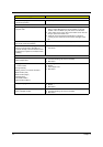
Label Component Label Component
JPW1 ATX 12V Power Connector JCI1
Chassis Intrusion Switch Connector
CPUFAN1 Processor Fan Connector JBAT1 Clear CMOS Jumper
D_LED1
D Bracket 2 Connector
JBIOS1 BIOS Flash Jumper
COM1 9-pin Serial Port JRECOVER System Recovery Switch Connector
FDD1 FDD Connector USB2/3 Front USB Connectors
ATX1
20-pin Power Connector
PCI1~3 Peripheral Component Interconnecto Slots
IDE2/1 Ultra ATA HDD Connectors
IDE1: Primary IDE Connector
IDE2: Secondary IDE Connector
JAUD1 Front Panel Audio Connector
SYSFAN1
System Fan Connector
CD1 CD-In Connector
SATA1/2
Serial ATA HDD Connectors
JLAN1 LAN Jumper
JFP1 Front Panel Connectors AGP1 Accelerated Graphics Port Slot
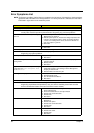
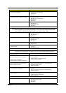
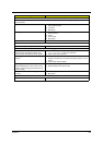
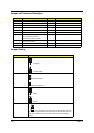
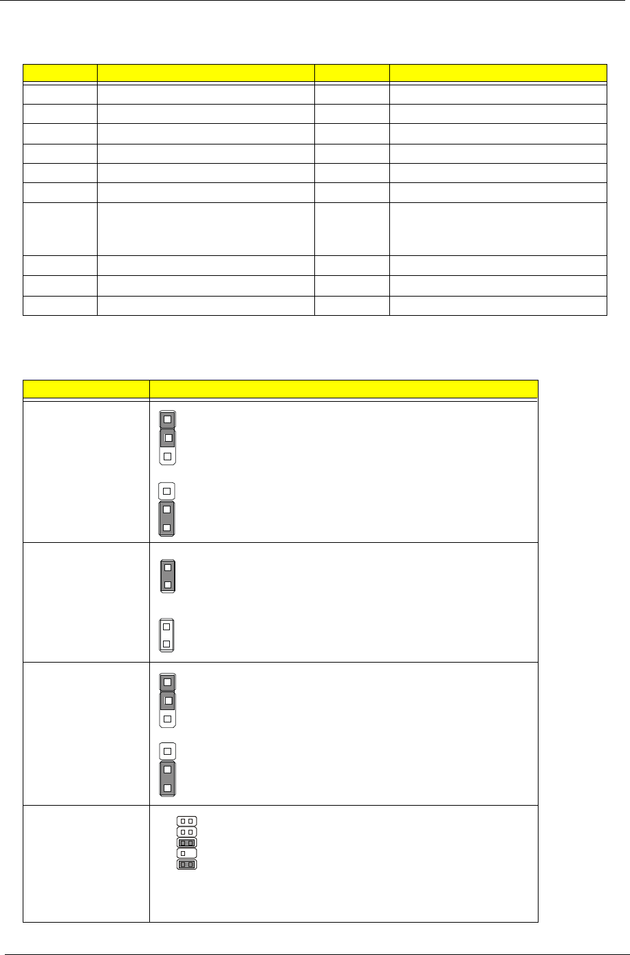
Jumper Function and settings
JBAT1
1-2 Normal*
2-3 Clear CMOS
JBIOS1
BIOS Flash Locked*
BIOS Flash Unlocked
JLAN1
Enable
Disable
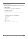
JAUD1
If you do not want to connect to the front audio header, pins 5 & 6,
9 & 10 have to be jumpered in order to have signal output directed to the rear
audio ports. Otherwise, the Line-Out connector on the back panel will not
function.
1
3
1
3
1
3
1
3
5
6
10
9