


14628 Central Blvd,
Chino, CA91710
tel:909.597.7588, fax:909.597.1939
© Copyright 2011 Acnodes, Inc.
All rights reserved. Product description and product specifications
are subject to change without notice. For latest product information,
please visit Acnodes’ web site at www.acnodes.com.
PC 6415
15” Fanless Panel PC
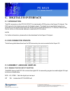
C. DIGITAL I/O INTERFACE
C.1 INTRODUCTION
The DIO connector on the PC5153/ PC5173 is interfaced to GPIO ports on the Super I/O chipset. The
DIO has both 4-bit digital inputs and 4-bit digital outputs. The digital inputs and digital outputs are
generally control signals that control the on/off circuit of external devices or TTL devices. Data can be
read or written to the selected address to enable the DIO functions.
NOTE:
For further information, please refer to the datasheet for the Super I/O chipset.
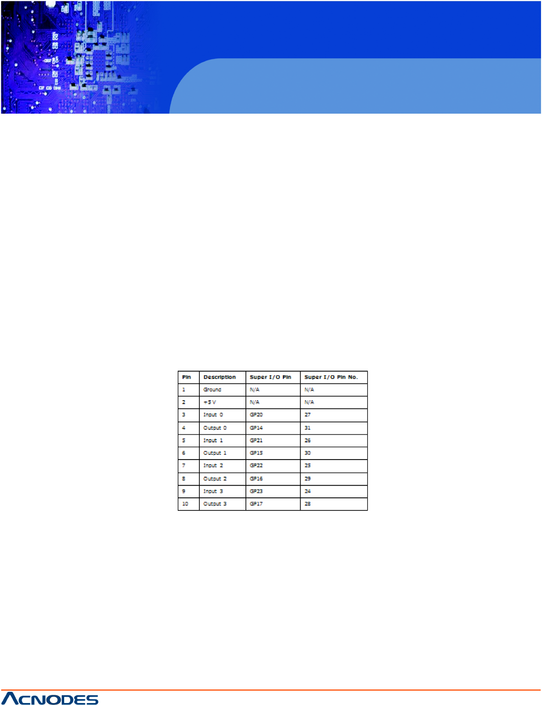
C.2 DIO CONNECTOR PINOUTS
The following table describes how the DIO connector pins are connected to the Super I/O.
C.3 ASSEMBLY LANGUAGE SAMPLES
B.3.1 ENABLE THE DIO INPUT FUNCTION
The BIOS interrupt call INT 15H controls the digital I/O. An assembly program to enable digital I/O input
functions is listed below.
MOV AX, 6F08H Sets the digital port as input
INT 15H Initiates the INT 15H BIOS call