ADCP-80-570 • Issue 2 • March 2006
Page 5
© 2006, ADC Telecommunications, Inc.
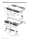
Each of the power buses supports seven circuit breaker positions including two 10 Amp circuit
breaker positions and five 5 Amp circuit breaker positions giving a total capacity per bus of 45
Amps.
When a circuit breaker trips, the input power bus is disconnected from the corresponding output
circuit.
1.5 Input Voltage
The dual bus circuit breaker panel can accommodate either –24 Vdc on both buses or –48 Vdc on
both buses.
The voltage level is sensed by the circuit breaker panel circuitry. The input voltages used with
the circuit breaker panel can fall within the following ranges:
• –24 Vdc nominal, within range of –21 Vdc to –30 Vdc
• –48 Vdc nominal, within range of –42 Vdc to –56 Vdc
1.6 Input Connectors
Each power bus has two input connectors on the rear of the circuit breaker panel through which
input power is provided. The two input power connectors are labeled “BATT” (battery) and “RTN”
(return). Each input connector consists of a pair of 0.25-inch (0.635 cm) studs (with nuts) mounted
on a plastic terminal block. Each pair of studs can accept different size 2-hole compression lugs used
with a range of wire sizes up to #6 AWG copper wire. Two 2-hole lugs per bus for use with #6 AWG
wire (four total) are provided with the circuit breaker panel. Additional lugs are available as
accessory items. Maximum lug width is 0.62 inches (1.6 cm). In selecting the copper wire size to be
used for power input, consider the allowable ampacity as defined by local practice and the National
Electrical Code (refer to Appendix A).
1.7 Output Voltage
The output voltage will be the same as the applied input voltage.
1.8 Output Connectors
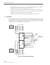
Each bus has two screw-down terminal strips with seven 8-32 screws each on the back of the
panel. The upper terminal strip contains the BATT (power feed) connectors. The lower terminal
strip contains the RTN (return) connectors. When a piece of equipment is connected to the
circuit breaker panel, it is connected to one BATT connector and one RTN connector located
vertically above and below one another.
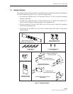
Warning: Use of one bus only on a dual bus panel will result in false alarms for the unused bus.
Power is required on both buses on a dual bus panel for normal operation.


