ADCP-80-570 • Issue 2 • March 2006
Page 23
© 2006, ADC Telecommunications, Inc.
6. Use a heat gun to apply heat to the heat shrink insulation until it tightens around the wire
and barrel end of the terminal.
7. Use the nuts (with captive washers) provided to secure the input power wires to the
specified terminals.
8. Connect the negative inputs to the negative (BATT) terminals on the A and B input power
terminal blocks.
9. Connect the positive inputs to the positive (RTN) terminals on the A and B input power
terminal blocks.
10. Use a torque wrench (with a 7/16-inch socket) to tighten the input power terminal block
nuts to 32 pound-force inches (3.6 Newton meters) maximum of torque.
11. Route the free ends of the input power cables to the office battery source.
12. Connect the input power cables to the office battery power source in accordance with
applicable local electrical codes and/or National Electrical Codes. Refer to Appendix A.
Do not apply power to the circuit breaker panel until instructed to do so for testing (see
Section 5).
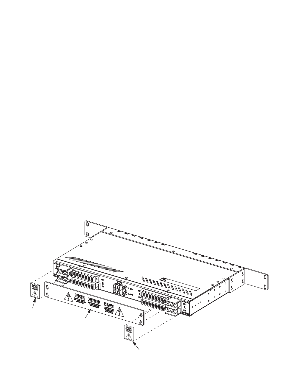
4.12 Installing Protective Covers
1. Snap the two small protective covers on the input and output terminals (Figure 18).
2. Fasten the large cover to the four corners of the output power terminal blocks using the
four #6-32 screws provided.
Figure 18. Installing Protective Covers
20644-A
COVER FOR
OUTPUT POWER
TERMINALS
COVER FOR
INPUT POWER
TERMINALS
COVER FOR
INPUT POWER
TERMINALS


