ADCP-80-570 • Issue 2 • March 2006
Page 20
© 2006, ADC Telecommunications, Inc.
5. If connecting bare wire, wrap the bare wire around the contact in a clockwise direction.
6. Tighten the screws to approximately 9 pound-force inches (1 Newton meter) of torque.
7. Terminate the other ends of the wires at the appropriate terminals in the external alarm
system.
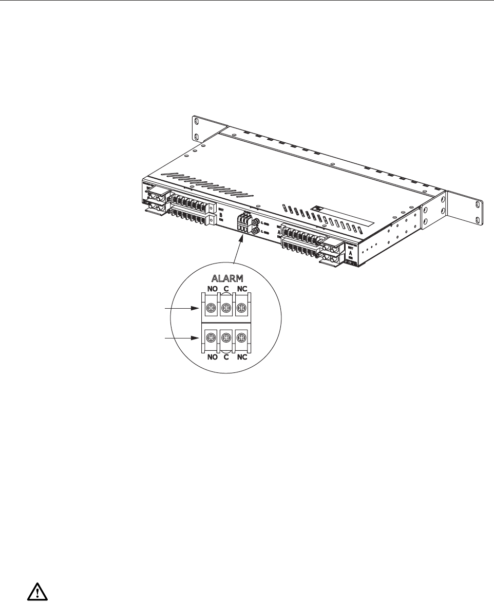
Figure 15. Alarm Terminals
4.10 Connecting Output
Output power is supplied to the protected equipment through the output power screw-down
terminal strips located on the rear of the panel. Wire leads should be equipped with crimp-on
spade lugs or ring connectors that have a minimum width of 0.32 inches (81.3 mm). The
terminals also accommodate copper wire without lugs (insulation stripped back). The terminals
can accept a variety of wire sizes up to #12 AWG with crimp-on spade lug or ring connectors or
wires in sizes from #12 AWG to #22 AWG with insulation stripped back. Follow local code. In
selecting wire size, refer to Appendix A.
.
1. Obtain the required lengths of wire for use as the output power cables.
2. Equip wire leads with spade or ring-type compression lugs (maximum width 0.32 inches)
or prepare a bare wire contact.
Caution: Connecting the equipment to the wrong circuit may cause damage to the
equipment or the circuit breaker panel.
SCREW-DOWN TERMINAL
ALARM CONNECTIONS
20641-A
SCREW-DOWN TERMINAL
CONNECTIONS FOR
REMOTE ALARMS


