


Overview 150-409-115-05, Issue 5
4 January 26, 2000 EDU-409 List 1
The physical location of the doublers is driven by the following three
deployment rules:
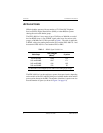
1 Place the enclosures at the electrical limits, 35 dB, of each span. This
places the first doubler at the 35 dB location, the second at 70 dB, and so
on, allowing the maximum circuit range to be realized.
2 If Rule 1 is not applicable, then try to make all spans the same electrical
length (same 260 kHz loss). This minimizes the maximum span loss and
assures maximum operating margin, resulting in optimal transmission
performance on the HDSL cable pairs. If specific application constraints
preclude using Rule 2, or if two different circuit layout choices have the
same maximum span loss, then use Rule 3.
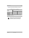
3 If Rules 1 and 2 are not applicable, make the spans closer to the ELU as
short as possible while making the spans farther from the ELU as long as
possible. This choice minimizes the I
2
R loss in the cable pairs, and
reduces the thermal stress on the ELU. Following this rule minimizes the
power consumption and dissipation of the ELU that provides the doubler
power.
Caution must be observed when pushing doubler spans to
their 35 dB maximum range. Refer to ADC’s Technical
Advisory #TA-015 on HiGain operating ranges and general
deployment guidelines.
Only those ERUs that have a local powering option can be
used in local ERU-powered applications.