


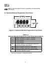
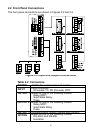

2.2 Front Panel Connections
The front panel connections are shown in Figures 2.2 and 2.3.
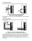
Figure 2.2 Input and Output Connections
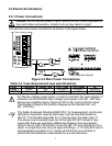
Table 2.2 Connectors
POWER AC/DC Power Connector: All models
INPUT
Input Connector:
All models TC, PR (Process), RTD
OUTPUT 1 Based on one of the following models:
Relay SPDT
Solid State Relay
Pulse
OUTPUT 2 Based on one of the following models:
Relay SPDT
Solid State Relay
Pulse
OUTPUT 3 Isolated Analog Output (Voltage and Current)
OPTION
Based on one of the following models:
RS-232C and RS-485
Excitation
1 23456789
10
6