


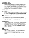
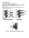
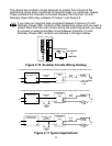
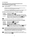

This device has snubber circuits designed to protect the contacts of the
mechanical relays when it switches to inductive loads (i.e. solenoids, relays).
These snubbers are internally connected between the Common (C) and
Normally Open (NO) relay contacts of Output 1 and Output 2.
If you have an inductive load connected between Common (C) and
Normally Closed (NC) contacts of the mechanical relays and you want to
protect them from the rush current during the switching period, you have
to connect an external snubber circuit between Common (C) and
Normally Closed (NC) contacts as indicated in the figure below.
Figure 2.10 Snubber Circuits Wiring Hookup
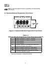
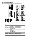
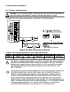
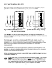
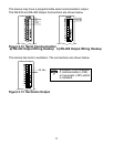
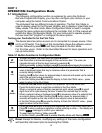
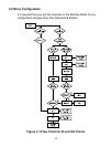
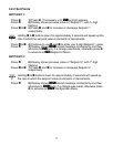
Figure 2.11 Typical Applications
TEMPERATURE
CONTROLLER
CONTROL
SIDE
dc INPUT
SSR
ac INPUT
SSR
ac INPUT
SSR
LOAD
SIDE
HEATER
Vac
Vac
dc CONTROLLED SSR USED WITH TEMPERATURE CONTROLLER WITH dc VOLTAGE SSR DRIVER OUTPUT
FAST BLOW
FUSE
0 or 5 Vdc,
TYPICALLY
4
3
1
2
TEMPERATURE
CONTROLLER
CONTROL
SIDE
LOAD
SIDE
HEATER
Vac
Vac
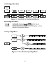
ac CONTROLLED SSR USED WITH TEMPERATURE CONTROLLER WITH MECHANICAL RELAY OUTPUT
FAST BLOW
FUSE
Vac
DRIVING
SSR
4
3
1
2
TEMPERATURE
CONTROLLER
CONTROL SIDE
LOAD
RESISTOR
LOAD
SIDE
HEATER
Vac
Vac
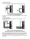
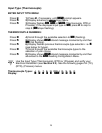
ac CONTROLLED SSR USED WITH TEMPERATURE CONTROLLER WITH TRIAC OUTPUT
FAST BLOW
FUSE
Vac
DRIVING
SSR
4
3
1
2
RC CIRCUIT
OR
VARISTOR
275 V
C
NC
NO
C
NC
NO
OUTPUT 1 OUTPUT 2
100
1/4 W
0.033
12