


52
ALARM 2 DISPLAY COLOR SUBMENU:
Press
d
11) Display flashes previous selection for “Alarm 2 Color Display”.
Press
b
12) Scroll through the available selections:
GRN
,
RED
or
AMBR
.
Press
d
13) Display shows
STRD
stored message momentarily and then
momentarily shows the software version number, followed by
RST
Reset, and then proceeds to the Run Mode.
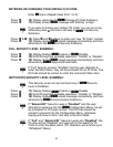
IN ORDER TO DISPLAY ONE COLOR, SET THE SAME DISPLAY
COLOR ON ALL THREE SUBMENUS ABOVE.
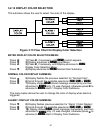
If user wants the Display to change color every time when both Alarm 1
and Alarm 2 are triggered, the Alarm values should be set in such a way
that Alarm 1 value is always on the top of Alarm 2 value, otherwise value
of Alarm 1 will overwrite value of Alarm 2 and Display Color would not
change when Alarm 2 is triggered.
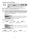
Example 1:
Output 1 & Alarm 2: SSR
Alarm Setup: Absolute, Above, Alarm 2 HI Value “ALR.H” = 200, Alarm 1
HI Value “ALR.H” = 400
Color Display Setup: Normal Color “N.CLR” = Green, Alarm 1 Color
“1.CLR” = Amber, Alarm 2 Color “2.CLR” = Red
Display Colors change sequences:
GREEN RED AMBER
•
--
➤
------------------------------
•
-----------------------------
•
------------------------------
➤
0 AL2.H = 200 AL1.H = 400
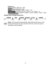
Example 2:
Output 1 &
Alarm 2: Pulse
Alarm Setup
: Absolute, Below, Alarm 2 Low Value “ALR.L” = 300, Alarm 1
Low Value “ALR.L” = 100
Color Display Setup
: "N.CLR" = Green, "1.CLR" = Amber, "2.CLR" = Red
Display Colors change sequences:
AMBER RED GREEN
•
--------------
•
----------------------------------
•
------------------------------------------- --
•
0 AL1.L = 100 AL2.L = 300
➤ ➤