


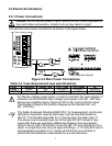
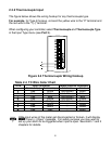
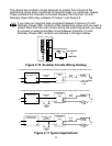

2.3.2 Thermocouple Input
The figure below shows the wiring hookup for any thermocouple type.
For example, for Type K hookup, connect the yellow wire to the "2" terminal and
the red wire to the "1(-)" terminal.
When configuring your controller, select Thermocouple and Thermocouple Type
in the Input Type menu (see Part 3).
Figure 2.4 Thermocouple Wiring Hookup
If the input wires of the meter get disconnected or broken, it will display
+OPN “Input (+) Open” message. For safety purpose you may want to
set up your alarm to be triggered when input is open. See Alarm 1 and 2
chapters for details.
8
TYPE Input Connector Jacket (external insulation)
Terminal 1 (-) Terminal 2 (+) Extension Grade
J Red White dark-Brown Black
K Red Yellow dark-Brown Yellow
T Red Blue dark-Brown Blue
E Red Purple dark-Brown Purple
N Red Orange dark-Brown Brown
R Red Black - Green
S Red Black - Green
B Red Gray - Black
Table 2.4 TC Wire Color Chart