


Chapter 2. Installation
26 NxT1 HSSI/V.35 User Manual 61200771L1-1
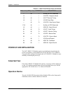
POWER UP AND INITIALIZATION
The NxT1 HSSI/V.35 Module requires no initialization input during the
power-up sequence, as described in the ATLAS 800 Series User Manuals.
Any previously configured setting for the NxT1 HSSI/V.35 Module is auto-
matically restored upon power-up.
Failed Self-Test
If the NxT1 HSSI/V.35 Module fails self-test, a message will be displayed
on the LCD and the terminal menu self-test log during power-up. See the
appropriate ATLAS 800 Series User Manual for details.
Operation Alarms
The red ALARM LED (located with the Module LEDs on the front panel)
illuminates when an alarm condition is detected.
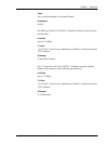
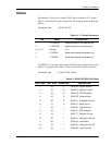
PIN (+ side) PIN (- side) DIRECTION DESCRIPTION
— 39 — Ancillary to DCE (Reserved)
14 — I V.35 RTS - Request to Send
15 40 I V.35 TT Terminal Timing
16 41 I V.35 SD Send Data
— 42 O V.35 DCD - Data Carrier Detect
17-18 43 — Ancillary to DCE (Reserved)
19 44 — HSSI SG - Signal Ground
20 45 O V.35 ST - Send Timing
21 46 O V.35 RT - Receive Timing
22 47 O V.35 RD - Receive Data
23 — O V.35 CTS - Clear to Send
— 48 I V.35 Ground/Present
24 49 O HSSI TM - Test Mode
25 50 — HSSI SG - Signal Ground
Table 2-2. HSSI/V.35 (SCSI-50) Pinout (Continued)