


Chapter 3. Operation
61200771L1-1 NxT1 HSSI/V.35 Module User Manual 37
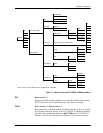
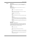
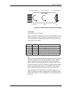
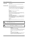
Figure 3-4. HSSI Interface Loopback Test Diagram
LA
AND
LB
(Not applicable in V.35 mode.)
Displays the status of the loopback circuit A and B signals. LA and
LB are asserted by the DTE to enable a loopback on the DCE and
its associated data communications channel. Four possible loop-
back options are available:
TA
Displays the status of the data Terminal equipment Available signal.
TA will be asserted by the DTE (independently of CA) when the
DTE is prepared to both send and receive data to and from the
DCE. Valid data transmission should not commence until CA has
also been asserted by the DCE. If the data communications channel
requires a keep alive data pattern when the DTE is disconnected,
then the DCE shall supply this pattern while TA is deasserted.
When using the NxT1 HSSI Module (1200346L2 only) in V.35
mode, TA displays the status of the Request to Send (RTS) signal.
When RTS is active in a V.35 configuration, Clear to Send (CTS) is
also active.
NxT1 HSSI
IMUX
T1 Interfaces
DTE
Local Line LoopbackRemote Line Loopback
Local DTE Loopbac
k
LA LB Loopback
Off Off No Loopback Active
On On Local DTE Loopback is Active
On Off Local Line Loopback is Active
Off On Remote Line Loopback is Active