


TRACER 2 x E1 User’s Manual
61280004L2-1C
Section 2 Installation
14
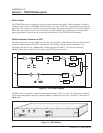
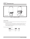
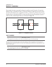
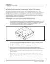
Three loopback functions are provided for diagnostic capability of each E1 interface. The local line
loopback (Loop 1 as illustrated in Figure 2-1) loops the incoming E1 signal back out at the E1 framer.
The remote link loopback (Loop 3 as illustrated in Figure 2-1) loops the E1 data back to the local end
from the remote end. This allows a BERT to be run across the microwave link and back. The local link
loopback (Loop 2 as illustrated in Figure 2-1) allows the local unit to loop E1 data back towards the
remote end. The available loopback functions are illustrated in Figure 2-1.
LINK PLANNING
I M P O R T A N T
The appropriate transmitter power must be calculated as part of the link planning.
The factors that must be taken into account when planning a link are optimal received signal level,
transmitter power, antenna feedline loss (each end), antenna gain (each end), free space path loss, and
required fade margin.
I M P O R T A N T
The optimal signal level for the receiver is -60 dBm.
Figure 2-1. E1 Loopback Locations
Local
E1
Remote
E1
RF Link21 3