


TRACER 2 x E1 User’s Manual
61280004L2-1C
Section 2 Installation
22
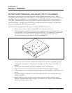
CO-LOCATING MULTIPLE SYSTEMS
When multiple transmitters are to be co-located (installed in the same equipment room or on the same
tower), it is advised to set all systems as follows:
1. If more than one system in the same frequency band is transmitting from the same location,
set the antenna polarity of one system horizontal and the other system(s) vertical. (The
antennas should be marked as to which mounting position is vertical or horizontal.) This
will provide approximately 30 dB of isolation between the different antennas.
2. If more than one TRACER system is installed, set the co-located transmitters to the same
frequency plan (example: Plan A or Plan B) and set each to a different spreading code. This
keeps the transmitters on the additional system(s) from interfering with the co-located
receiver(s).
3. If the systems are from different manufacturers, set the transmit frequencies as close as
possible with different spreading codes. Other manufacturers may not use the exact
frequency plans as the TRACER system, but keeping the frequencies close will reduce the
probability of the transmitter(s) interfering with the co-located receiver(s).
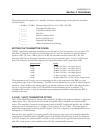
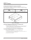
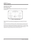
ANTENNA ALIGNMENT
After the transmitter power for each end has been adjusted and the BBP and RFC have been installed and
connected, the antenna should be connected to the RFC via the feedline. Verify that both antennas are
arranged on the same polarity: vertical or horizontal. The antennas should be aimed toward one another
as precisely as possible and the received signal strength indicator (RSSI) voltage measured. The RSSI
voltage is a function of the signal strength at the receiver and is used to measure the received signal
strength. RSSI varies approximately from 0 to >4 volts, with 0 volts corresponding to a weaker received
signal and 4 volts or better corresponding to a stronger received signal.
NOTE
The voltage level present at the RSSI test point represents a relative signal level of receive strength
from the far end. No direct correlation can be made between RSSI voltage level and actual receive
level in dBm. This test point is provided to assess relative signal level for alignment of antenna.
RF LOW
The “RF Low” LED indicates that the received signal is within 10dB of the minimum received signal
strength (RSL < approximately -80 dBm). If this indicator is on, the link performance may be marginal.
The antennas should be peaked in azimuth and elevation until the desired signal level is achieved. RSSI
may be monitored on either the RF unit or the front of the BBP. If the received signal is too strong and
RSSI reaches a maximum such that the peak cannot be discerned, then the transmitter on the far end
should be turned down.
At this point the radio link should be operational. Proper operation can be determined by the status of
the “LINK DOWN” LED. If this LED is on, the link is not operational. If this LED is not on, the link is
operating. Certain types of interference can cause one end of a path to operate and the other end to fail.
In some instances, this may be corrected by swapping the frequency plan at each end, thus avoiding the
interference if it is stronger at one end than the other. Changing the spreading code at each end may also
allow interference to be mitigated.