


TRACER 2 x E1 User’s Manual
61280004L2-1C
Section 2 Installation
17
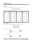
The nominal received signal level is -60 dBm. For help in link planning, use the path loss calculation
worksheet below.
- 89 dBm / -87 dBm Minimum Signal Power for 2.4 GHz / 5.8 GHz
+ _______ Transmitter Feedline Loss
- _______ Transmitter Antenna Gain
+ _______ Path Loss
- _______ Receiver Antenna Gain
+ _______ Receiver Feedline Loss
+ _______ Required Fade Margin
= _______ (dBm) Transmitter Power Setting
SETTING THE TRANSMITTER POWER
The FCC specifies the maximum transmitter power that may be used for antennas of a given gain. FCC
rules Part 15, Subpart 247 allow for a maximum power of 1 watt into antennae of a gain less than or
equal to 6 dBi. For every 3 dB of gain over 6 dBi, the transmitter must be reduced by 1 dB. The
following table lists the maximum transmitter power for given antennae gains. For the 5.8 GHz band,
there is no reduction in transmitter output power required for antenna gains greater than 6 dBi.
Antenna Gain Power
6 dBi 30 dBm (2.4 GHz, 1 watt output option)
12 dBi 28 dBm (2.4 GHz, 1 watt output option)
18 dBi 26 dBm (2.4 GHz, 1 watt output option)
24 dBi 24 dBm (2.4 GHz, 1 watt output option)
30 dBi 22 dBm (2.4 GHz, 1 watt output option)
36 dBi 20 dBm (TRACER, 2.4 GHz, 100 mw output option)
The transmitter power is set by way of a momentary switch on the front panel of the BBP or via the
configuration page of the VT100 interface. The RFC must be attached by way of the IF cable during this
operation. Attach an RF power meter to the N-type antenna connector on the RFC, and adjust the power
by way of the front panel switch or VT100 until the desired transmitter power is obtained. If a
mastmount RF converter is used, the transmitter power adjustment should be made before the RFC is
installed on the mast.
2.4 GHZ, 1 WATT TRANSMITTER OPTION
The 2.4 GHz TRACER model is offered with a standard +20 dBm power output or optional 1 watt power
output option. The 1 watt option provides an add-on amplifier that is installed in the rackmount RFC
chassis. This amplifier is connected to the transmit cable of the RFC module and amplifies the +20 dBm
output power to a maximum level of +30 dBm (1 watt), factory set to +27 dBm. The output power is
proportional to the output level from the RFC module. The level is adjusted via the Baseband Processor
front panel or VT100 terminal.
Because the 1 watt amplifier is frequency specific, the frequency plans can not be manually changed by
swapping the TX and RX cables in the RFC chassis as described in the following section. If a frequency
reversal is required, the rackmount RFCs will have to be relocated to the opposite ends of the microwave
path. The 1 watt option is only available for the 2.4 GHz, rackmount RF converter.