


33
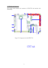
3.1.3 Headers and connectors pin definition
Because the board size limitation & wants to keep the flexible of I/O connector
placement,
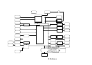
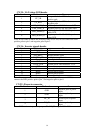
The following lists are I/O pin definitions of PCM-7230 SBC. All the pin headers’
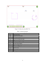
pin order is the same as the figure. As you see, the first pin has a white mark on PCB.
Except the pin headers, all the other connectors have white mark at 1
st
pin.
34
45
67
21
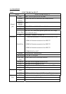
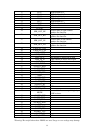
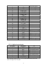
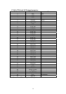
The following tables are the pin definition of all the connectors on PCM-7230
SBC.
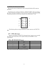
JP 1 : CPLD JTAG port
there are two CPLDs on PCM-7230. Advantech doesn’t suggest users to modify
the CPLD code. If users have to do it, please contact your distributor or sales
representative.
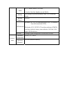
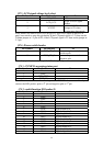
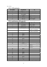
JP 2 : CPU PXA255 JTAG port
Pin Number Pin function
Ps.
1 TCK
2 TDI
3 TDO
4 TMS
5 nJTAG_TRST
6 nRESET
Note: Users can use this port to modify the bootloader.