


41
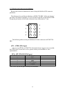
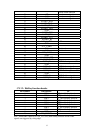
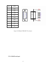
3.1.9 LCD inverter connector for 5V inverter(CN26, Pin1~Pin4)
Connect the PCM-7230 with the 5V inverter for adjusting LCD panel’s brightness.
The voltage range of this signal is from 0 to 5V. When enable backlight is on, the
voltage of this signal is 5V; otherwise is 0V. Brightness voltage is adjustable by
Advantech SW utility.
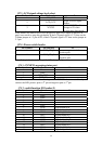
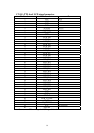
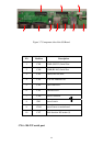
3.1.10 Audio connector(CN3,P25~P36)
The PCM-7230 provides audio signals on pin25 ~ pin36 of CN3. These audio signals
include Microphone in (mono), Line in/out (stereo) and two speaker-out function.
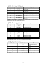
3.1.11 Battery and DC power status monitor connector(CN31)
With this connector, the PCM-7230 can monitor and report the battery and DC power
status thru I2C bus.
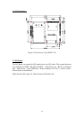
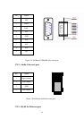
3.1.12 4-wire touch-screen connector(CN9,Pin29~Pin32)
Connect the PCM-7230 with the 4-wire touch-screen. The PCM-7230 supports 4-wire
resistive touch-screen. Figure 3.7 shows the cable connected to this connector.
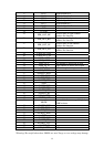
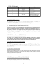
3.1.13 8 DI,8 DO pin header (CN3,Pin7~Pin24) & GPIO pin header(CN12)
This connector connects the PCM-7230 with the 8 DI & 8 DO. The PCM-7230 has
8-channel digital inputs,8-channel digital outputs and 8 GPIO pins. The GPIO is
default for hotkey function.
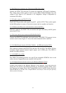
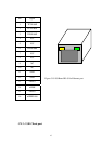
3.1.14 PCMCIA slot (U10)
The PCM-7230 default provides one type II hot-swappable PCMCIA slots in the
solder side for CompactFlash card, wireless LAN card, etc.
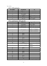
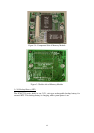
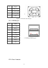
3.1.15 100-pin board-to-board connector for Memory Module (CN14)
Another issue related to the Memory Module is boot priority. Users may put your
image files into flash on the Memory Module by Advantech upgrade utility. Users
may also put your image files in the CompactFlash card as another choices and boot
from PCMCIA or CF slots.
The CompactFlash card always comes the first priority
when system is booting.