


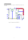
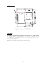
39
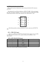
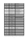
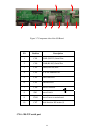
CN 20 : LAN status LED header
Pin Number Pin function Ps.
1 CF_VR
compact flash slot LED indicator,
positive pole
2 CF_RDY
compact flash slot LED indicator,
negative pole
3 LED_LINK_P positive pole of LAN link status LED
4 LED_LINK_N negative pole of LAN link status LED
5 LED_SPEED_P
negative pole of LAN 10/100 speed
status LED
6 LED_SPEED_N
negative pole of LAN 10/100 speed
status LED
Note: If user wants to know the accessing status of CF slot, he can connect the LED
positive pole to pin 1 and negative pole to pin 2.
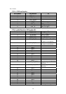
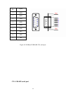
CN 26 : Inverter signals header
Pin Number Pin function Ps.
1 SYS_VCC +5V
2 GND
3 ENVBK5V inverter enable signal
4 BLCTRL_SW backlight strength switch
5 Resev. reserve pin for future
6 GND
7 Power_LED System power LED indicator. +3.3V
8 GND
9 Resev. reserve pin for future
10 Resev. reserve pin for future
11 Resev. reserve pin for future
12 Resev. reserve pin for future
Note: If user wants to know the system power status by self-connected LED, he can
connect the LED positive pole to pin 7 and negative pole to pin 8.
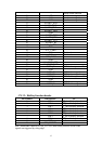
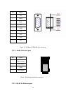
CN 29 : Power-in connector
Pin Number Pin function Ps.
1 GND
negative pole of power
input
2 GND
negative pole of power
input
3
DC_IN positive pole of power
input
4
DC_IN positive pole of power
input
Note: CN29 is the main power input port. The DC_IN range is 10V ~ 28V.