31
common ground is connected to pin 5. Furthermore, an input signal can be used
to shut down the UPS (5 VDC – 12 VDC.)
PIN-OUT NO. DESCRIPTION N.C.-N.O. POSITION
1 Shutdown signal + -
2 Shutdown signal – -
3 Configurable Not connect
4 Discharge - Mains failure N.C.
1
5 Common -
6 Equipment in Bypass N.O.
2
7 Low battery N.O.
8 General alarm N.O.
9 Discharge - Mains failure N.O.
1
N.C.: Normally closed contact. On the alarm having activated the contact
is opened.
2
N.O.: Normally open contact. On the alarm having activated the contact
is closed.
4.3.6. COM-INTERFACE RS232 AND RS485, CONNECTOR (X31)
The serial communications interface operates over low voltage. To ensure safe and
trouble-free communication, install at a safe distance from the power supply lines
to the UPS.
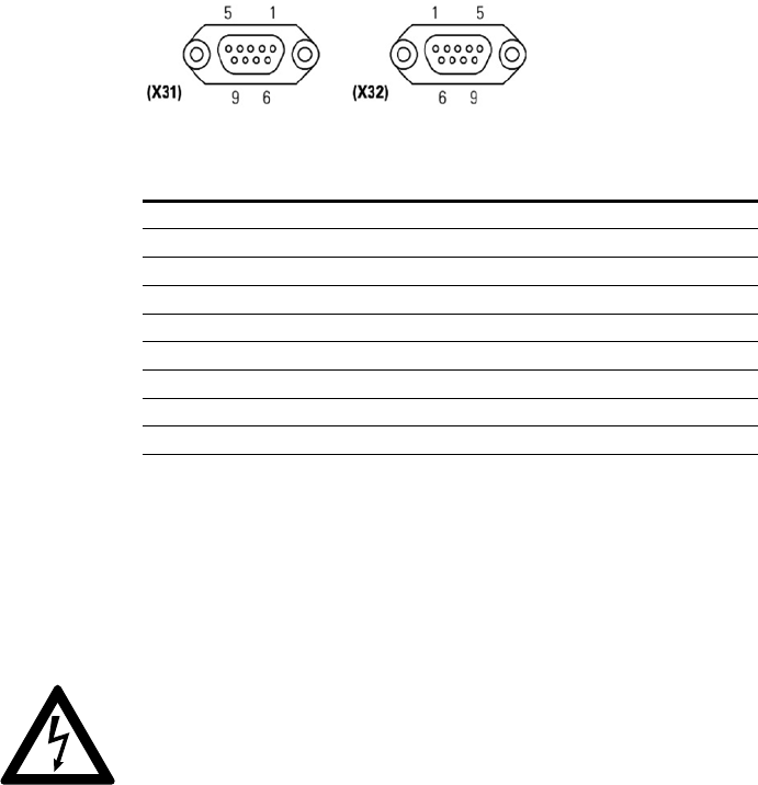
The X31 DB9-connector is used for communication to RS232 or RS485 standard
connectors. Both standards cannot be used simultaneously.
Both channels are in use for connecting the UPS with any machine or devices that
has this standard bus. The RS232 consists of the transmission of serial data, so it is
possible to send a large amount of information through a communication cable of
just 3 wires.
Table 2: Alarms interface to relays connector DB9 (X32)
Fig.21: Connector DB9 (X31) & (X32)


