33
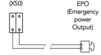
4.3.7. EPO TERMINALS (X50)
The equipment has two terminals ready for external remote (Emergency Power
Off (EPO)).
In case where there is a requirement to install a switch or button (EPO), the cable
bridge that closes the circuit has to be removed from terminal strip (X50).
The switch or button (EPO) has to open the circuit between the terminal strip
(X50) to activate the emergency shutdown. To restore the UPS to normal mode,
reverse the position of the switch or button (EPO), -close the circuit in terminal
strip (X50).
To understand the operation of (EPO), see section 5.3 of this manual.
Note: In a parallel system there is an emergency stop switch to one of the two
UPS devices. Detailed information on emergency shutdown can be found in
chapter 5.6.
4.3.8 PARALLEL BUS CONNECTION (X36)
This section is only relevant for parallel systems.
• For the correct parallel operation both UPS communicate to each other via the
parallel BUS. For redundancy purposes the BUS connection consists of 2 cables
which are connected in a loop.
• Connect the parallel BUS connection after all power connections have been
done. In the accessory of each UPS you can find one 5 meters, 15-pole parallel
BUS cable (HDB 15 connector male/female). If you connect 2 UPS to one
parallel system each UPS comes with one cable.
• Connect X36o of UPS 1 to X36i of UPS 2 and X36i of UPS 1 to X36o of UPS 2.
An additional termination of the connection is not needed.
Fig.22: Terminals for connection of external push-button (EPO), property of the user


