69
(*) DSP internal error can happen for the following reasons:
• Watchdog failure.
• Wrong ADC measures.
• Communication errors between DSP and processor.
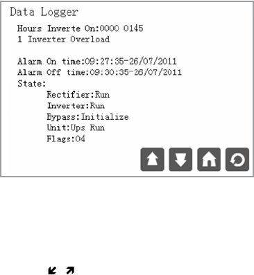
Fig.32: Screen 5.0 “Data logger”
The first line indicates the inverter runtime from the first unit startup. This counter
accumulates the total inverter running time from the beginning; it is not possible
to reset it.
Using the ( ), ( ) keys, you can move throughout the differ
ent registers of this historic
file. The data logger file can save up to 100 historic registers.
Alarm on and off time.
The first row displays the date and time when the alarm occurred:
• hh: hour of alarm activation
• mm: minutes of alarm activation
• ss: seconds of alarm activation
• dd: day of alarm activation
• mm: month of alarm activation
• yy: year of alarm activation
The second row displays the date and time when the alarm was deleted:
• hh: hour of deleted alarm
• mm: minutes of deleted alarm
6.3.6. ‘‘DATA LOGGER” LEVEL (SCREEN MENU 5.0)


