57
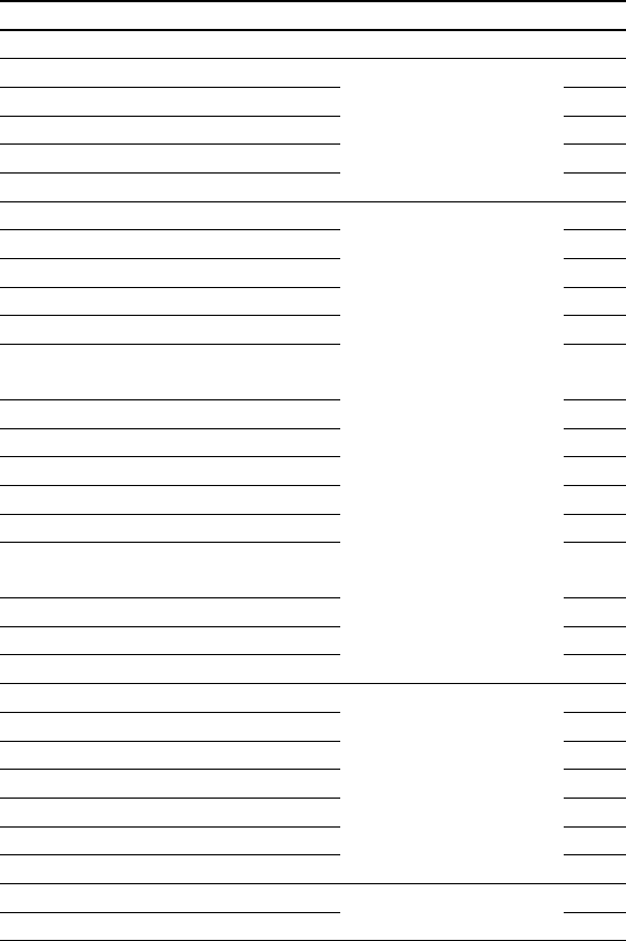
The illustration shows some examples of messages that may be displayed. Table 4
contains a list of all of the warning messages that can be displayed.
REPRESENTATION IN DISPLAY LCD ALARMS FOR NO.
Rectifier overload Rectifier 1
Inverter overload
Inverter
2
Mains failure, low battery level 3
Inverter voltage out of margins 4
DC voltage detected at the output. 5
Maintenance bypass. inverter not available 6
Battery discharging
UPS
7
High temperature. Reduce output load. 8
Battery switch open. Switch it ON. 9
Bypass failure. Not synchronized inverter. 10
Unit on bypass. Initialise UPS. 11
Some unit(s) blocked due to maintenance
bypass.
12
CAN BUS 1 Communication failure. 13
CAN BUS 2 Communication failure. 14
End of battery life. 15
Battery temperature too high. 16
Battery test not succeeded. 17
Battery disconnection. Shutdown &
restart.
18
Mains phase rotation. UPS start disabled. 19
Bypass phase rotation. UPS start disabled. 20
EEPROM failure. 77
Input voltage wrong. Rectifier stop.
Rectifier stops
21
Rectifier desaturation. Rectifier stop. 22
DSP internal error. Rectifier stop. 23
Input phase rotation. Rectifier stop. 24
DC BUS voltage wrong. Rectifier stop. 68
Parallel system rectifier stop 69
Cont. Test fail rectifier stop. 75
Inverter desaturation. Inverter stop.
Inverter stops
25
Inverter overload. Inverter stop. 26


