


10
3.3 Processing the setpoint Thyro-Step Controller
Only local setpoints, no bus setpoint
Analog input at control terminal X6.1 or X6.4 (depending on X6.7) of the TSC
> Do not connect anything to terminal X2.1 of the power controller.
- The bus module is fully functional. The analog signal from the control terminal X6.1 or X6.4 is used as
setpoint.
Setpoint from the bus module (X22.3), no local setpoint
> Connect the ground to terminal X2.1 of the TSC.
- The master setpoint of the Ethernet bus module is used.
Bus setpoint, switching over to “local” in case of bus fault
Only use the setpoint of the bus module if there is an IO connection.
> Connect terminal X2.1 of the TSC to one of the terminals X1.1 to X8.1 of the bus module.
- If there is an IO connection the master setpoint is used. If there is no IO connection then the analog
setpoint is used.
Switching over to bus / local setpoint value switchable for each controller in operation
Individual setpoint from the bus module for each power controller.
> Connect terminal X2.1 of the power controller to one of the terminals X1.5 to X8.5 of the bus module.
- The power controllers can be switched over individually (targeted) via the bus between master setpoint
and the analog setpoint.
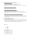
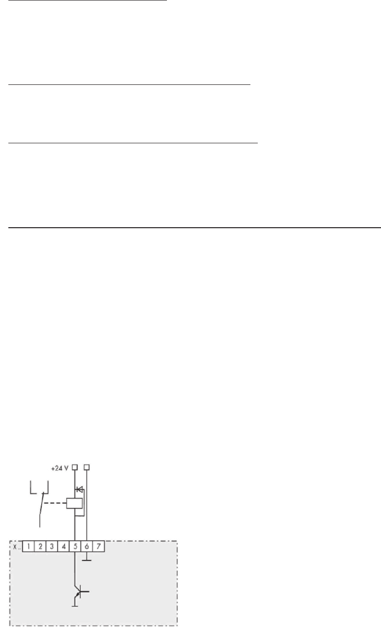
3.4 Freely addressable digital outputs
> As long as the terminals X1.5 to X8.5 of the bus module are not being used for switching over the set-
point, these can be used as switch outputs.
> Connect the relay to a 24 V DC coil voltage for free use. The idle circuit is integrated. The actuating
current is a maximum 120 mA per output. As a result it is possible to switch over, for example, the room
ventilators, anti-condensation heating, circuit breakers or control lamps via the bus.
Relais Control