


Document No. DER-S0008A 5 Version 1.0 ©2008 DMC Co., Ltd.
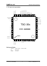
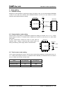
TSC-30/IC Product S
p
ecification
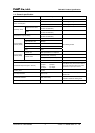
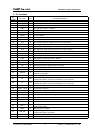
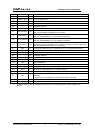
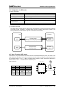
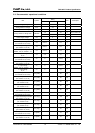
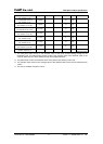
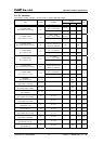
3. Pin functions
Pin
number
Pin name I/O Functional description
1 PANEL_AD_XL I Touch Screen XL input pin.
2 PANEL_AD_XR I Touch Screen XR input pin.
3 SW0 I SW0 input pin; H=ON=1, L=OFF=0.
4 SW1 I SW1 input pin; H=ON=1, L=OFF=0.
5 I Unused pin. Via resistance; Vcc is connected.
6 I Unused pin. Via resistance; Vcc is connected.
7 CNVss P Vss is connected.
8 RESET I Reset input pin (active L).
9 Vcc P Power supply input pin; Vcc is connected.
10 Vref P A/D converter reference voltage input pin; Vcc is connected.
11 Vss P Power supply input pin (GND); GND is connected.
12 Xin I Clock input pin; When using external clock, clock is input to this pin.
13 Xout O Clock output pin; When using external clock, this pin is opened.
14 Vcc P Power supply input pin; Vcc is connected.
15 Vss P Power supply input pin (GND); GND is connected.
16 LED0 O LED output pin; When internal initialization was finished correctly, output L.
17 LED1 O LED output pin; Touch input, ON=L, OFF=H.
18 LED2 O LED output pin; When a response for the command is NAK, output L.
19 O Unused pin; Opened.
20 Vss P Power supply input pin (GND); GND is connected.
21 Vcc P Power supply input pin; Vcc is connected.
22 Vcc P Power supply input pin; Vcc is connected.
23 USBVref P
USB reference voltage input pin. If Vcc is 3.3V, Vcc is connected. If Vcc is 5V, GND is
connected via capacitor.
24 TrON O Identification signal for USB. D+ is connected via resistance (1.5k ohm).
25 D+ I/O
Data send/receive pin; In USB mode, D+ pin.
In serial mode, GND is connected via resistance (1k to 10k ohm).
26 D- I/O
Data send/receive pin; In USB mode, D- pin.
In serial mode, GND is connected via resistance (1k to 10k ohm).
27 PANEL_YD/LL O Touch screen control pin.
28 PANEL_YU/UL O Touch screen control pin.
29 PANEL_XL/UR O Touch screen control pin.
30 PANEL_XR/LR O Touch screen control pin.
31 PANEL_LL O Touch screen control pin. Used only in 5-wire mode. In 4-wire/8-wire mode, opened.
32 PANEL_UR O Touch screen control pin. Used only in 5-wire mode. In 4-wire/8-wire mode, opened.
33 O Unused pin; Opened.
34 O Unused pin; Opened.
35 RxD_I I
In power-save mode, start signal input pin by command reception. Only used serial
communication mode.
36 BEEP O BEEP output pin; H output.
37 USB_PW I
USB power supply detection pin. In USB mode, USB-Vbus is connected. *1
In serial mode, GND is connected.
38 PEN_UP I GND is connected.
39 PANEL_THOb3 I/O Touch screen control pin. Used only in 5-wire mode. In 4-wire/8-wire mode, opened.