Programming the Agilent 603xA Power Supplies Using Basic
125
Protection Functions
Overvoltage
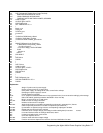
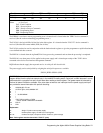
The trip level of the overvoltage protection circuit can be read by sending the device command "OVP?" and entering the
result.
If the overvoltage protection circuit has tripped the supply can be reset by sending the "RST" device command .
Foldback
In certain applications, it may be desirable to have an overcurrent protection similar in function to the over-voltage
protection.
An application of this feature might occur in the testing of P.C. board subassemblies. Using the power supply as a bias with
current limit only could cause tracks to lift off the board in the event of a short circuit through a small track.
Using the CC foldback mode could prevent the supply from passing excessive currents through a shorted track by disabling
the supply when constant current mode is entered .
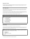
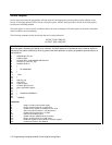
To enable the CC foldback mode, send the power supply the device command "FOLD CC".
A reciprocal foldback function with CV operation as the trip condition can be enabled with the device command "FOLD
CV”. "FOLD OFF" disables either.
Soft Programming Limits
The supply can be directed to ignore commands to program voltage and current above predefined levels. Applications of the
function might include programs which program the supply based on an unknown input and development and debugging of
new test programs. Advantages of the programming limits include ease of programming and maintenance of a limit which
remains when the program is no longer running.
Maximum programming values for voltage and current can be set with the "VMAX" and "IMAX" device commands if
present output voltage or current does not exceed desired limits.
A subsequent attempt to program voltage or current above the soft limits will result in an error.
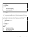
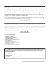
To set the maximum voltage allowable to 10 volts and maximum current to 1 amp, issue the following statement:
OUTPUT @PS;"VMAX l0;IMAX 1"
A subsequent attempt to program voltage above l0 volts or current above 1 amp will result in an error.
Fault Indicator (FLT) and Inhibit (INH)
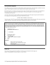
FLT and INH provide additional shutdown protection features should the GP-IB or controller fail. Both FLT and INH are
independent of the SRQ function available through the GP-IB, and are accessed through a rear panel jack.
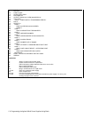
FLT is an output circuit (TTL compatible) which provides the user with a means of knowing the status of any unmasked
fault register bit.
INH is an input circuit (TTL compatible) which provides a way to disable the supply remotely.


