Operating Instructions
47
Holding the LCL switch in for one second causes the power supply’s GP-IB address to be displayed on the front panel until
the switch is released or two seconds elapse.
The address switches are also used during troubleshooting to select which self tests are run in test mode. If the power
supply has been serviced be certain to check the GP-IB address switches. Note that the top two switches are not address
switches. Be careful to use only the five bottom switches for setting the address.
Power-On Service Request
The power supply can request service from the controller when power is turned on. Power-on service request (PON SRQ) is
enabled or disabled by the rear-panel PON SRQ switch, and cannot be controlled by commands via GP-IB. The service
request bit is reset by a serial poll, regardless of whether set by power-on or some other cause. To enable power-on to
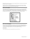
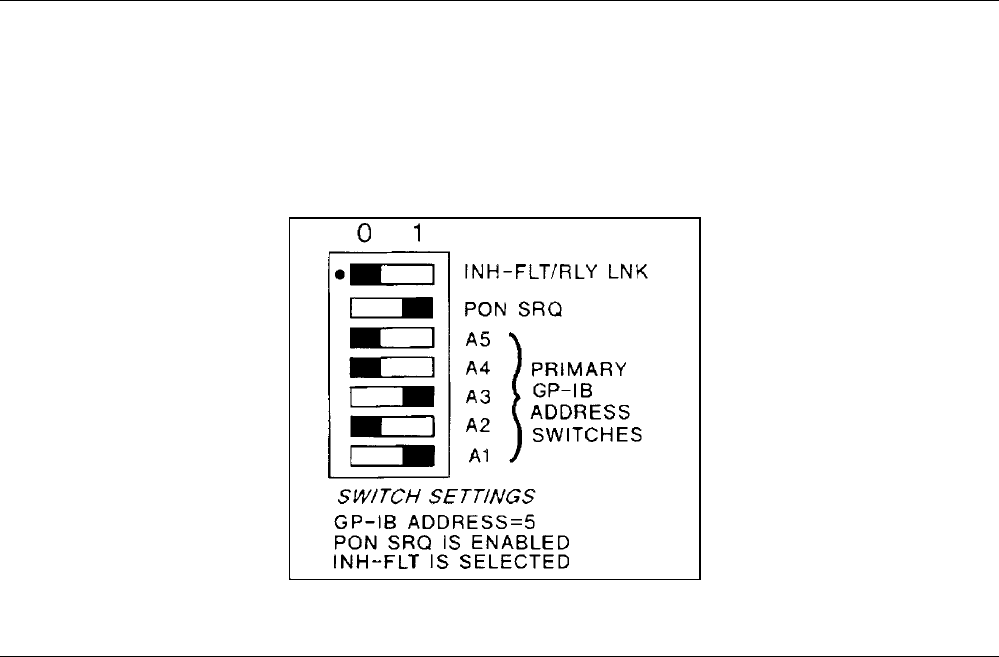
request service, set the PON SRQ switch to "1", as shown in Figure 3-8. If enabled, PON SRQ will request service when the
power supply is turned on or any time a momentary input power dropout causes the power supply to re-initialize.
Figure 3-8. GP-IB Address/PON SRQ Switches
INH-FLT or RLY LNK Operation
The four-pin connector on the GP-IB board can be configured for either Fault Input (FLT) and Remote Inhibit (INH)
operation or for operation with the Agilent 59510A or 59511A Relay Accessory. Setting the INH-FLT/RLY LNK switch to
"0" (see Figure 3-8) selects INH-FLT operation as described on page 70. Setting the switch to "1" selects RLY LNK
operation (see instructions supplied with the relay accessory and also Appendix C in this manual).
Initial Conditions
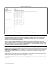
The power supply initializes at power on programmed with the values listed in Table 3-6.


