Operating Instructions
67
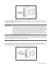
Figure 3-10. Voltage Programming of Output Voltage
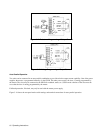
Constant Current Output, Resistance Control
. The setup shown in Figure 3-12 allows the output current to be varied by
using an external resistor to program the supply. The discussion on Page 56 for constant voltage operation also applies for
constant current operation.
If the programming terminals (IP to P) become open circuited during resistance programming the
output current will tend to rise above rating. The power supply will not be damaged if this occurs, but
the user’s load may be damaged. If there is a possibility that the programming leads may be opened, it
is suggested that the optional resistor be connected directly across terminals IP and
P, as shown in
Figure 3-12. The value of this resistor should be selected to limit the output current to the maximum
that the load can handle without damage. For example, if the load can handle half the full current
rating of the power supply, a 2000 ohm resistor should be connected from IP to
P. Of course, if
this resistor is used, the resistance value actually programming the supply is the parallel combination
of the programming resistor and the optional resistor.
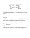
Constant Current Output, Voltage Control. The setup shown in Figure 3-13 allows the output current to be varied by using
an external voltage to program the supply. The discussions on the previous page also apply for constant current operation.
The previous note also applies also to programming output current.
Multiple-Supply Operation
The power supply can be operated in combination with other power supplies to provide increased output capability. Auto-
parallel operation of two power supplies can provide up to twice the output current. Other configurations are possible.
Contact Agilent Technologies, Power Products Division for specific application assistance.
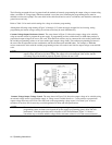
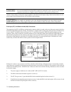
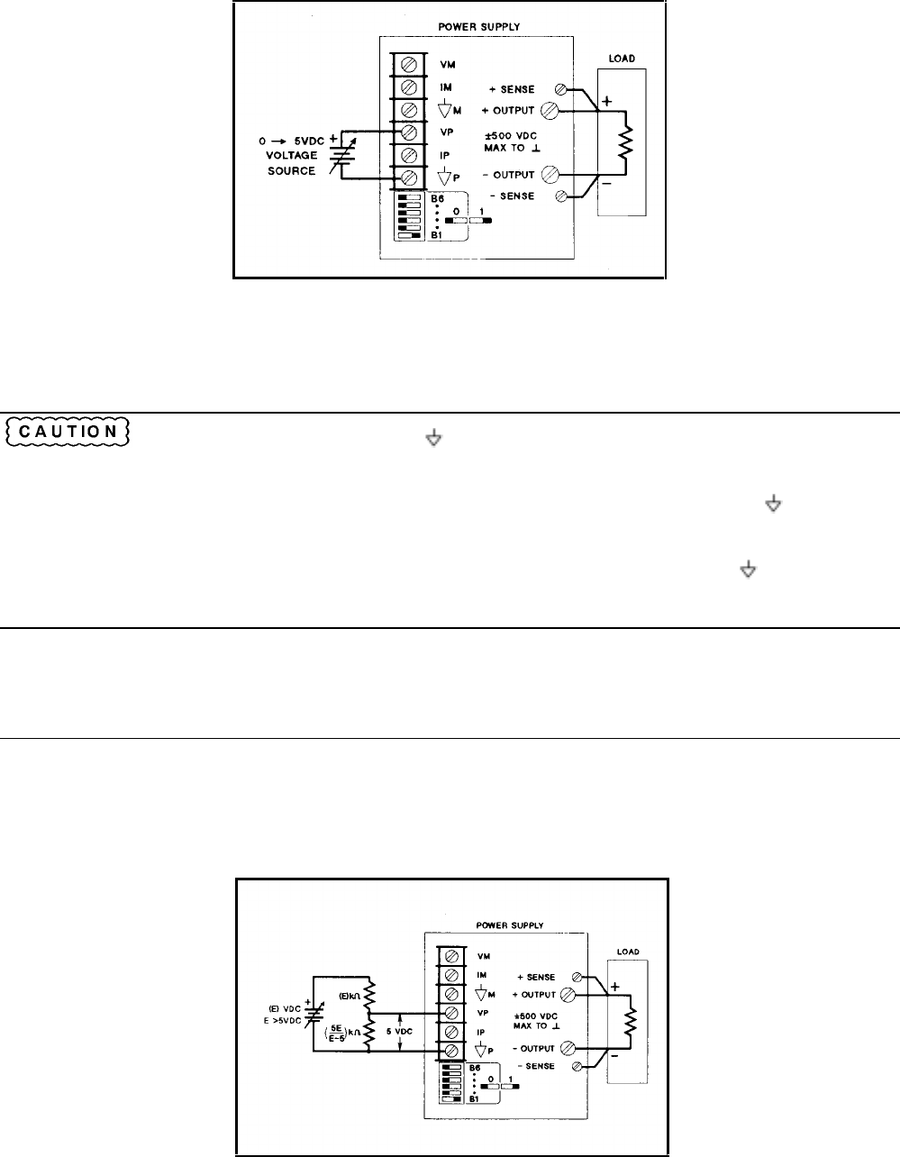
Figure 3-11. Optional Voltage Divide for Program Source


