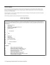
Programming the Agilent 603xA Power Supplies Using Basic
126
Advanced Topics
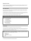
Hold Mode
At times it may become necessary to program several power supplies synchronously. The hold mode provides advantages
over other less precise means of synchronous programming. With hold mode, functions with first and second rank are all
loaded into first rank buffers. When triggered with the "TRG" or "T" device commands or the group execute trigger
interface management command, second rank is loaded. Voltage and current settings, foldback and mask register have dual
rank storage.
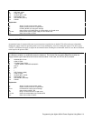
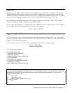
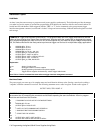
EXAMPLE 9: Trigger three supplies synchronously. This program makes use of the trigger hold feature to load the
buffers of three supplies then trigger them simultaneously. Note that while the supplies will be triggered at the same
time, programming speed can vary from unit to unit so that supplies may not meet final output voltage simultaneously.
Still, this method would offer the most precise synchronous trigger over the bus for multiple bias supply applications.
10 ASSIGN @Ps1 TO 701
20 ASSIGN @Ps2 TO 702
30 ASSIGN @Ps3 TO 703
40 ASSIGN @All_ps TO 701, 702, 703
50 OUTPUT @All_ps; “CLR;HOLD ON”
60 OUTPUT @Ps1; “VSET 12; ISET 3”
70 OUTPUT @Ps2; “ISET 4; VSET 2;FOLD CC”
80 OUTPUT @Ps3; “ISET .15:VSET 5"
90 OUTPUT @All_ps;''TRG; HOLD OFF"
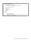
Explanation:
10-40: Assign I/O path names
50: Set trigger holdoff on all three supplies
60-80: Send programming information to the power supplies
90: Trigger all three supplies simultaneously, release trigger holdoff mode
Note: TRG or T device command has same effect as trigger interface management command
Machines States
The power supply can store up to 16 complete states and recall them in arbitrary order. Storing a state involves taking a
"snapshot" when the command is received. The following statement stores a state in register 10 and recalls register 4:
OUTPUT @PS;"STO 10;RCL 4"
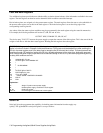
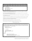
EXAMPLE 10: Program using machine states to set up output. This method of setting up the output
saves some time in processing the commands and facilitates repeating the same commands. A burn-in program
would be and ideal use of this function.
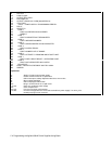
10 ! PROGRAM T0 CYCLE 0N FIVE VOLTAGE SETTINGS
20 !
30 ASSIGN @Ps TO 705
40 OUTPUT @Ps:"CLR;OUT OFF"
50 !
60 ! NOTE: OUT OFF COMMAND NAT STORED IN
70 ! SNAPSHOT BUT DOES DISABLE SUPPLY
80 !
90 ! STORE THE FIVE STATES
100 !
110 OUTPUT @Ps:"VSET 1:ISET 20:STO1"
120 OUTPUT 2Ps:"VSET 2:ISET l0:F0LD CC:STO2"


