


Copyright 2002 Agilent Technologies. 10001810-E6701A Tutorial LAN Connection
All Rights Reserved.
Page 9 of 32 Rev. 1.2; Feb. 14, 2002
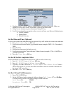
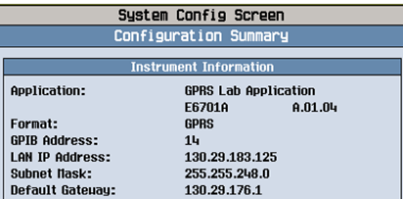
4. Find the test set’s LAN IP Address, Subnet Mask, and Default Gateway. If they are
already set to non-zero values, record their values on the lines below.
5. If they are not already set, press Instrument Setup (F1) key.
6. Scroll down and set the appropriate values as received from your Network Administrator:
• LAN IP Address
• Subnet Mask
• Default Gateway
Set the Date and Time (Optional)
If you set the correct date and time here, then protocol logs will include the correct date and time.
1. Press Instrument Setup (F1) key
2. Scroll down and set the Date in yyyy.mm.dd format (example: 2002.11.5 = November 5,
2002).
3. Press the knob
4. Edit the date, then press the knob to set it.
5. Scroll down and set the Time in hh.mm 24-hour format (example: 17.46 = 5:46 PM) as
you did for the Date.
6. Press the Close Menu (F6) key.
Set the RF In/Out Amplitude Offset
Set this amplitude to compensate for the device’s RF test cable if necessary.
1. Press RF IN/OUT Amptd Offset (F5) key
2. Press RF IN/OUT Amptd Offset Setup (F2) key
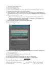
3. Typically, it is OK to leave the RF In/Out Amplitude Offset State Value =
Off for this tutorial. If it is On, check that reasonable values are entered in the table for
the device’s RF test cable.
4. Press the Close Menu (F6) key.
Set the Cell and Call Parameters
1. Press CALL SETUP key
2. On the Call Parms (right) column of softkeys, change Cell Power (F7) to –50 dBm.
For many devices the test set default settings should work fine:
Cell Band (F8): PGSM
Broadcast Chan (F9): 20