


AT-GS900/8PS Switch Installation Guide
55
Connectors and Port Pinouts
This section lists the connectors and connector pinouts.
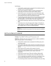
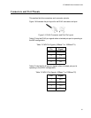
Figure 14 illustrates the pin layout for an RJ-45 connector and port.
Figure 14. RJ-45 Connector and Port Pin Layout
Table 12 lists the RJ-45 pin signals when a twisted pair port is operating in
the MDI configuration.
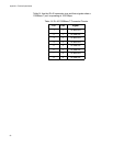
Table 13 lists the RJ-45 port pin signals when a twisted pair port is
operating in the MDI-X configuration.
Table 12. MDI Pin Signals (10Base-T or 100Base-TX)
Pin Signal
1TX+
2TX-
3RX+
6RX-
Table 13. MDI-X Pin Signals (10Base-T or 100Base-TX)
Pin Signal
1RX+
2RX-
3TX+
6TX-