


Installation and Safety Guide
13
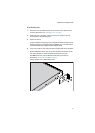
Warning When SBx908 devices are connected with VCS stacking cables (either
HS-STK-CBL or XEM-STK-CBL), each individual stack member chassis must be
additionally grounded by using the rear grounding-terminal on each device. In
order to avoid large circulating ground currents, the wires of each grounding
cable must be 18AWG or thicker.
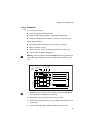
PWR01
DC
PWR01 DC
Power supply specifications:
■ functional range 40 to 60 V, 48 V nominal
■ supports either positive grounded or negative grounded operation
■ a 15 Amp certified/listed circuit breaker is required for circuit protection
Supply cable specifications:
■ tray cable should be UL listed Type TC tray cable (or equivalent)
■ three-core cable is required
■ minimum core size: 3.3 mm
2
(12 AWG) high strand count copper wire
■ minimum cable rating: 600 V, 90 degrees C
Warning Disconnect the power supply cable before starting this procedure.
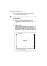
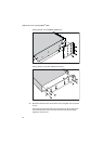
1. Remove the transparent protective terminal cover.
2. Strip the supply cable wires to expose 7.5 mm (0.31 in.) of bare conductor.
Terminate the wire with a nylon insulated solderless ring tongue terminal,
JST FN5.5-5 or equivalent, using a crimp tool.
3. Connect the ground wire to the ground terminal. Use the diagram on the
rear panel of the switch to identify terminals. Tighten the terminal to
between 2.4 and 4.0 Nm (21.3 and 35.4 lbf in).
4. Connect the positive feed to the + (positive) terminal and the negative feed
to the - (negative) terminal. Tighten the terminals to between 2.4 and
4.0 Nm (21.3 and 35.4 lbf in).
Note that the DC return input terminal must be connected as an Isolated
DC return (DC-I).
5. Ensure that there are no exposed cable strands.
6. Replace the cover. You must replace the transparent plastic terminal cover
before continuing.
7. Secure the supply cable to the rack framework or a similar object to ensure
that connections are isolated from any force applied to the cable.