


Installation and Safety Guide
15
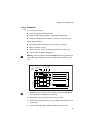
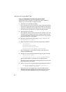
PWR05
DC
PWR05 DC
Power supply specifications:
■ functional range 40 to 60 V, 48 V nominal
■ supports either positive grounded or negative grounded operation
■ a 30 Amp certified/listed circuit breaker is required for circuit protection
Supply cable specifications:
■ tray cable should be UL listed Type TC tray cable (or equivalent)
■ three-core cable is required
■ minimum core size: 3.3 mm
2
(12 AWG) high strand count copper wire
■ minimum cable rating: 600 V, 90 degrees C
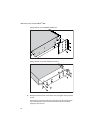
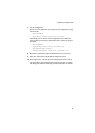
Warning When mounting one or two AT-PWR05 DC PSUs to a grounded rack,
ensure that the ground level of the rack and the DC power connector are the
same.
1. Ensure that the circuit breaker for the supply circuit and the Run/Standby
switch on the PSU are off (slide to position O).
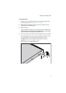
2. Plug the DC power cord into the power inlet on the PSU.
3. Connect the supply cable wires to the circuit breaker and switch the circuit
breaker ON.
4. Turn on the PSU by sliding in the Run/Standby switch to position 1.
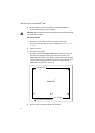
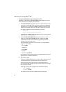
DC
IN
LED
RUN/STANDBY
SWITCH
CAPTIVE
SCREW
DC
OUT
LED
FAULT
LED
N/C
GREEN
( GND )
RED
( + )
BLACK
( - )