


x900 Series Switch and SwitchBlade
®
x908
8
■ All bare conductors must be coated with an appropriate antioxidant
compound before making crimp connections.
Warning Both AC and DC versions of this equipment must be earthed through
the power cables provided.
On a level surface
1. Ensure the area has sufficient space for the switch and its cables.
If you have not already done so, review considerations in “Selecting a Site”
on page 6.
2. Unpack the switch.
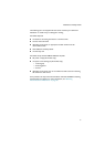
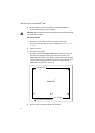
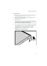
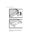
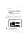
3. Fit rubber feet, if supplied.
All models except the SwitchBlade x908 ship with rubber feet. They stop
the switch from slipping and protect the surface from scratches. The
x900-12XT/S switch has four feet. All other models have five feet. Using the
screws provided, screw the rubber feet in the holes on the underside of the
switch. Use the following diagram to locate the screw holes. For the
x900-12XT/S, use positions 1, 2, 3, and 5.
4. Place the switch in the desired location for operation.
Front of Switch
Underside
Rear of Switch
Screw holes for rubber feet
12
345