


Product Description
11
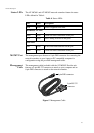
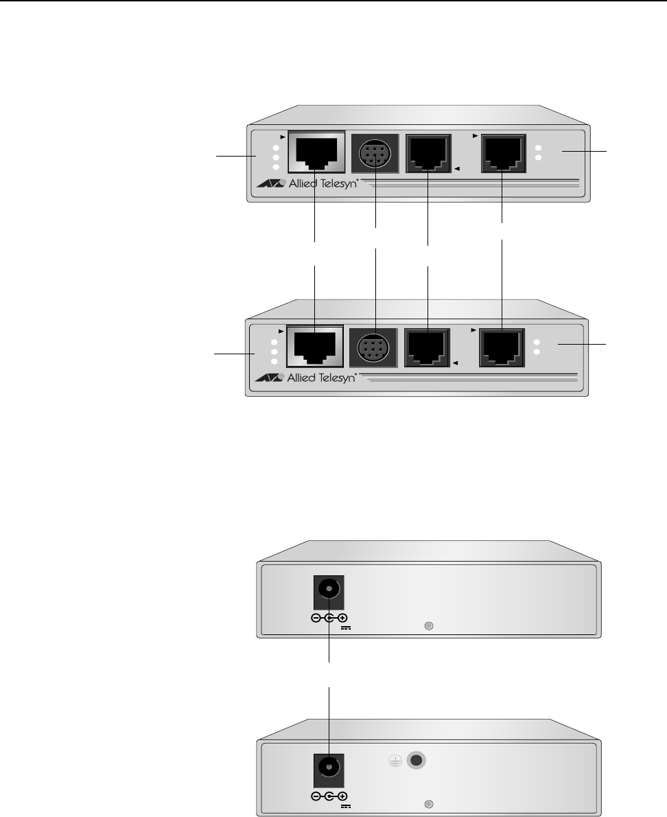
Location of Components
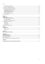
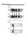
Figure 2 illustrates the front panels of the AT-MC601 and AT-MC602
network extenders.
Figure 2 Front Panels
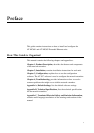
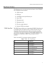
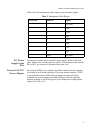
Figure 3 illustrates the rear panels of the AT-MC601 and AT-MC602
network extenders.
Figure 3 Rear Panels
LINE
10BaseT/
100BaseTX
PSTN
LINK
ACT
PWR
ERR
LINK
MGMT
AT-MC601
VDSL EXTENDED ETHERNET
Ethernet Port
Management Port
PSTN Port
VDSL Line
LEDs
VDSL Line Port
LINE
10BaseT/
100BaseTX
PSTN
LINK
ACT
PWR
ERR
LINK
MGMT
AT-MC602
VDSL EXTENDED ETHERNET
VDSL Line
LEDs
Ethernet
Status
LEDs
Ethernet
Status
LEDs
AT-MC601
AT-MC602
12VDC
DC Power Supply Port
12VDC
AT-MC601
AT-MC602