


Installation
27
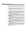
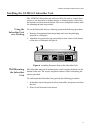
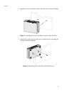
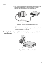
3. Next, connect a telephone line cable from the VDSL Line port to the
wall/interior telephone line, as shown in Figure 11, so that the
Subscriber unit can communicate with the Provider unit.
Figure 11 VDSL Line to Wall/Interior Phone Line
Note
The procedure for connecting the management cable is described in
”Cabling Preparations” on page 36.
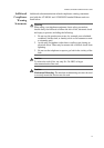
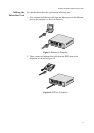
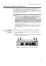
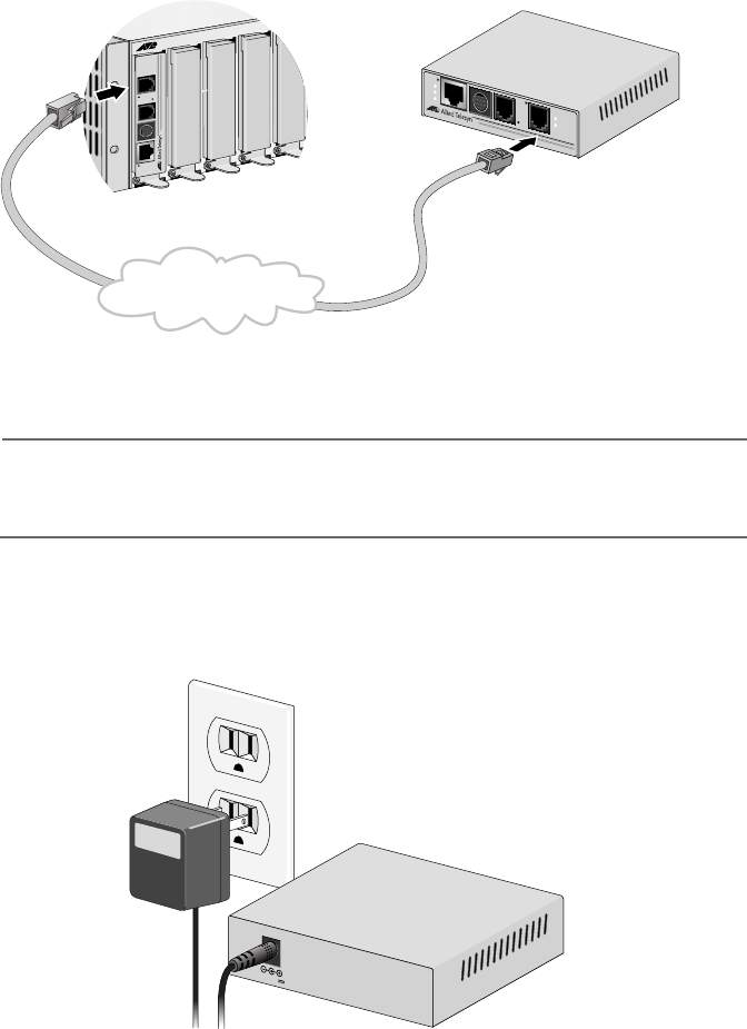
Powering On the
Subscriber Unit
Power on the Subscriber unit using the power adapter provided, as shown
in Figure 12.
Figure 12 Power On The Subscriber Unit
M
C
R
1
2
LINE
10BaseT/
100BaseTX
LINK
ACT
PWR
ERR
LINK
MGMT
AT-MC602
VDSL EXTENDED ETHERNET
PSTN
L
I
N
E
1
0
B
a
s
e
T
/
1
0
0
B
a
s
e
T
X
P
S
T
N
L
I
N
K
A
C
T
P
W
R
E
R
R
L
I
N
K
M
G
M
T
A
T
-
M
C
6
0
1
V
D
S
L
E
X
T
E
N
D
E
D
E
T
H
E
R
N
E
T
Wall/Interior Phone Line
1
2
V
D
C